Digital video monitoring cable for high-speed elevator and its installation and binding method

A digital video, high-speed elevator technology, applied in the direction of cable installation, cable installation device, insulated cables, etc., can solve the problems of damage, reduce the effect of video surveillance, etc., achieve high bending resistance, increased thickness, and ensure long-term reliability and safety The effect of effective use

Active Publication Date: 2017-08-29
GUANGZHOU CITY YU HUNG ELECTRIC WIRE & CABLE IND
View PDF1 Cites 0 Cited by
  • Summary
  • Abstract
  • Description
  • Claims
  • Application Information

AI Technical Summary

Problems solved by technology

[0004] The present invention solves the problem that existing high-speed elevator digital video surveillance cables have bending force generated by the cables themselves during the process of moving up and down with the elevator car, which is dispersed and consumed by the outer sheath and two strands of steel wire ropes. And the internal structure of the cable produces a large bending disturbance destructiveness, which affects the reduction of the video surveillance effect, and even causes the video surveillance system to fail in a short time. Anti-bending and disturbing force during the process, avoiding the damage of the cable by external force, ensuring the long-term safe use of the cable for high-speed elevator digital video monitoring cable and its installation and binding method

Method used


Image

  • Digital video monitoring cable for high-speed elevator and its installation and binding method
  • Digital video monitoring cable for high-speed elevator and its installation and binding method
  • Digital video monitoring cable for high-speed elevator and its installation and binding method

Examples


Embodiment 2

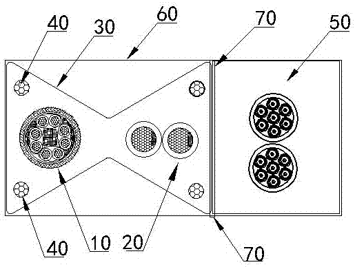
[0026] figure 2 , image 3 In the illustrated embodiment, the present invention provides a method for installing and bundling digital video monitoring cables for high-speed elevators, including the following bundling steps:

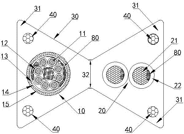
[0027] A step of arranging the high-speed elevator digital video monitoring cable described in any one of the above technical solutions in parallel with the elevator accompanying cable 50;

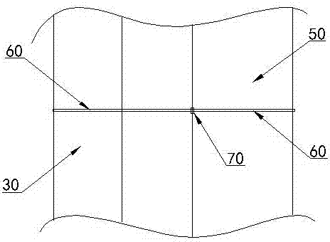
[0028] The horizontal binding step of horizontally binding the parallel-arranged high-speed elevator digital video surveillance cable and the elevator accompanying cable 50 with a binding strap; using the first cable tie 60 to horizontally bind the high-speed elevator digital video surveillance cable and the elevator accompanying cable together.

[0029] On the cable tie after horizontal binding, use the second cable tie 70 to extend into the gap between the digital video surveillance cable for high-speed elevators arranged in parallel and the elevator accompanying...


PUM


Abstract

The invention discloses a digital video monitoring cable for a high-speed elevator and an installing and binding method of the digital video monitoring cable. The digital video monitoring cable comprises a monitoring communication cable, an electrifying cable, four strands of anti-bending wire ropes and a butterfly outer sheath, wherein the butterfly outer sheath is in a butterfly outer sheath structure with two triangular grooves on the cross section; the butterfly outer sheath structure is formed by simultaneously removing an isosceles triangle inwards from each of two opposite sides of a rectangular frame; the monitoring communication cable and the electrifying cable are respectively arranged at the centre positions of two symmetrical triangles; the four strands of anti-bending wire ropes are symmetrically arranged at the positions at the inner sides of four vertex angles of the butterfly outer sheath structure respectively; the butterfly outer sheath and an elevator travelling cable are arranged in parallel and then are transversely bound by a transverse binding tape; and the transverse binding tape at the position of the gap between the butterfly outer sheath and the elevator travelling cable is vertically bound by a binding tape. Therefore, the anti-disturbance force of the cable in the high-speed up and down movement process is improved; damages caused by external force are avoided; and relatively long-term use of the monitoring cable is ensured.

Description

technical field [0001] The invention relates to a monitoring cable, in particular to a monitoring cable in high-speed elevator digital video monitoring and an installation and binding method thereof. Background technique [0002] With the emergence of more and more high-rise buildings, video surveillance equipment, such as surveillance cameras, advertising media video displays, etc., are installed in elevators; and these video equipment need video cables to provide safe and reliable transmission signals to ensure the safety of video equipment. work normally, but the cables installed in the existing high-speed elevators for digital video monitoring to transmit digital video signals are data communication cables. When the cable moves up and down with the elevator bridge car, the bending force generated by itself is dispersed and consumed by the outer sheath and the two strands of steel wire rope. The effect of video surveillance, and even the short-term failure of the video s...

Claims


Application Information

Patent Timeline
Patent Type & Authority Patents(China)
IPC IPC(8): H01B7/18H01B7/22H01B11/06H02G1/00
Inventor 汤代兵廖孝彪
Owner GUANGZHOU CITY YU HUNG ELECTRIC WIRE & CABLE IND
Why Eureka
Try Eureka