

Automatic charging device for intelligent door locks
An automatic charging device and smart door lock technology, applied in circuit devices, battery circuit devices, building locks, etc., can solve problems such as hidden dangers, lower user experience, and insufficient power of smart door locks, so as to achieve safe and secure use, and solve power problems Effects of Power Consumption and Charging Issues
- Summary
- Abstract
- Description
- Claims
- Application Information
AI Technical Summary
Problems solved by technology
Method used
Image

Examples
Embodiment 1
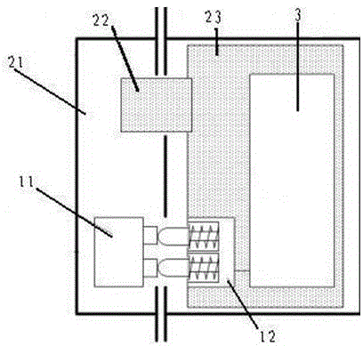
[0018] see figure 1 , Embodiment 1 of the present invention includes:
[0019] An automatic charging device for an intelligent door lock, comprising: a power supply, a mechanical lock body and a charging part 3, the power supply includes a power transmission part 11 and a power receiving part 12, the charging part 3 includes a rechargeable battery, and the mechanical lock body includes The lock shell 21, the lock tongue 22 and the lock body shell 23, the power transmission part 11 is fixedly connected in the lock shell 21, the power receiving part 12 is fixedly connected in the lock body shell 23, the When the deadbolt 22 is connected with the buckle shell 21, that is, when the door lock is in the locked state, the power transmission part 11 and the power receiving part 12 form a closed-circuit charging power supply circuit, and the deadbolt 22 and the buckle shell 21 When the phase is disconnected, that is, when the door lock is in the open state, the power transmission part...
Embodiment 2
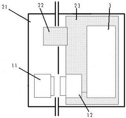
[0025] as attached figure 2 Shown, its difference with embodiment 1 is:
[0026] The power transmission part 11 and the power receiving part 12 are connected by a contactless wireless power transmission part. The power transmission part 11 converts electric energy into electromagnetic waves and sends them to the power receiving part 12. The power receiving part 12 converts the energy transmitted by the electromagnetic waves into Charge the rechargeable battery for electric energy output.
[0027] Different from the prior art, the beneficial effects of the intelligent door lock automatic charging device of the present invention include:
[0028] (1) Realize the function of charging the rechargeable battery of the smart door lock when the door lock is locked, and automatically stop charging when the door lock is opened, which can provide sufficient power supply for the door lock,
[0029] (2) There is no need to replace the battery, which solves the problem of power consumpti...
PUM
 Abstract
Description
Claims
Application Information