a reciprocating mechanism

A technology of reciprocating and stopping mechanisms, which is applied in the direction of mechanical equipment, belts/chains/gears, transmission devices, etc., can solve the problems of motor output torque drop, unstable driving load capacity, insufficient motor voltage compensation, etc.

Active Publication Date: 2017-06-30
SUZHOU RUIPENGCHENG SCI & TECH CO LTD
View PDF5 Cites 0 Cited by
  • Summary
  • Abstract
  • Description
  • Claims
  • Application Information

AI Technical Summary

Problems solved by technology

However, the common frequency converter has insufficient voltage compensation for the motor when outputting low frequency, and the torque increase of the motor is not enough, resulting in a decrease in the output torque of the motor and unstable load capacity.
Especially in the process of frequent starting, stopping and reversing at low speeds, ordinary inverters do have shortcomings, and it is necessary to redesign the mechanical transmission mechanism to achieve a more ideal transmission.

Method used


Image

  • a reciprocating mechanism
  • a reciprocating mechanism
  • a reciprocating mechanism

Examples


Embodiment Construction

[0038] The present invention will now be further described in detail in conjunction with the accompanying drawings and embodiments. These drawings are all simplified schematic diagrams, only illustrating the basic structure of the present invention in a schematic manner, so it only shows the composition related to the present invention.

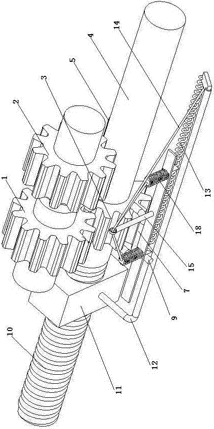
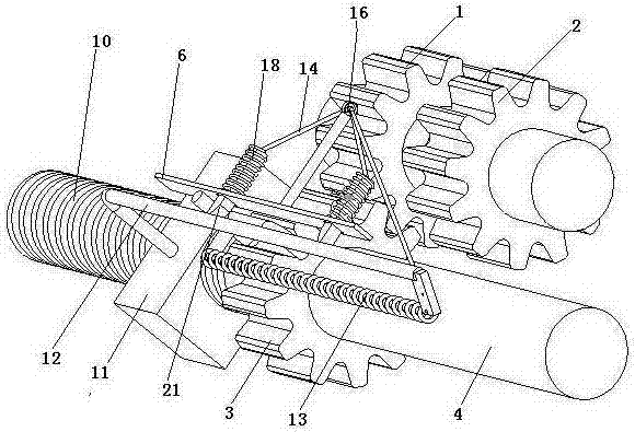
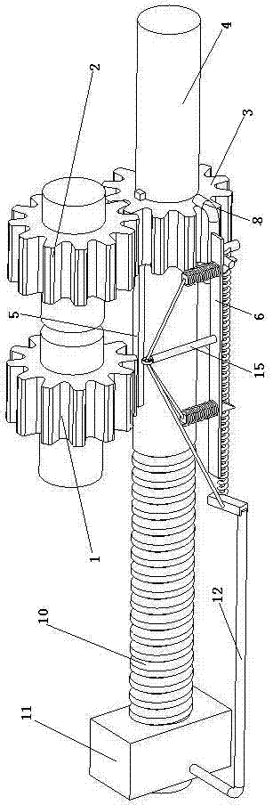
[0039] Such as Figure 1-4 As shown, a reciprocating mechanism includes: a drive mechanism and a toggle mechanism connected by a shift fork 7,

[0040] - The drive mechanism includes a drive gear 3 that can mesh with the first gear 1 and the second gear 2 respectively, the drive gear 3 is slidably arranged on the drive shaft 4, the first gear 1 and the second gear 2 The direction of rotation is opposite;

[0041] - The toggling mechanism includes a fixed plate 6, and the shift fork 7 includes two shift fork rods 8 symmetrically arranged on the same side and a shift rod 9 on the other side, and the two shift fork rods 8 are respectively locat...


PUM


Abstract

The invention relates to a circulating mechanism which comprises a drive mechanism and a toggle mechanism. The drive mechanism and the toggle mechanism are connected through shifting forks. The drive mechanism comprises a drive gear capable of being engaged with a first gear and a second gear. The drive gear is arranged on a drive shaft in a sliding manner, and the rotating direction of the first gear is opposite to that of the second gear. The toggle mechanism comprises a fixed plate. Each shifting fork comprises two shifting fork rods symmetrically arranged on the same side and a stop lever arranged on the other side, the two shifting fork rods of each shifting fork are located on the outer sides of the two ends of the drive gear respectively, and the stop levers can be connected with stop mechanisms. A screw rod is arranged at one end of the drive shaft, and a screw sleeve connected with one end of a bent rod is arranged on the screw rod in a threaded sleeving manner. The two stop mechanisms are arranged on the fixed plate, and a ferrule rod is arranged at the position, between the two stop mechanisms, of the fixed plate. Flexible ropes connected with the free end of the bent rod pass through a ferrule on the ferrule rod and then are divided into two strands to be connected with the stop mechanisms respectively. The two ends of a first spring are connected with the free end of the bent rod and the shifting forks respectively.

Description

technical field [0001] The invention relates to a transmission conversion mechanism, in particular to a reciprocating mechanism. Background technique [0002] The transmission conversion mode of modern power mechanism is mostly carried out by means of frequency converter to control the motor. The frequency converter controls the speed of the motor and controls the steering of the motor, which makes the speed output of the motor to the transmission mechanism extremely flexible. However, the common frequency converter has insufficient voltage compensation for the motor when outputting low frequency, and the torque boost of the motor is not enough, resulting in a decrease in the output torque of the motor and unstable load capacity. Especially in the process of frequent start, stop, and reverse at low speeds, ordinary frequency converters do have shortcomings, and the mechanical transmission mechanism needs to be redesigned to achieve a more ideal transmission. Contents of th...

Claims


Application Information

Patent Timeline
Patent Type & Authority Patents(China)
IPC IPC(8): F16H37/12
CPCF16H37/124
Inventor 吴凡邵金发
Owner SUZHOU RUIPENGCHENG SCI & TECH CO LTD
Why Eureka
Try Eureka