A modification mechanism capable of automatic drilling

A technology of a driving mechanism and a toggle mechanism, which is applied to boring/drilling devices, drilling/drilling equipment, parts of boring machines/drilling machines, etc., and can solve problems such as high labor intensity and low labor efficiency

Active Publication Date: 2017-10-10
宁波贝递同步带有限公司
View PDF4 Cites 0 Cited by
  • Summary
  • Abstract
  • Description
  • Claims
  • Application Information

AI Technical Summary

Problems solved by technology

This method is labor-intensive and low-efficiency for mass production of shaft holes, especially for through-holes.

Method used


Image

  • A modification mechanism capable of automatic drilling
  • A modification mechanism capable of automatic drilling
  • A modification mechanism capable of automatic drilling

Examples


Embodiment Construction

[0047] The present invention will now be further described in detail in conjunction with the accompanying drawings and embodiments. These drawings are all simplified schematic diagrams, only illustrating the basic structure of the present invention in a schematic manner, so it only shows the composition related to the present invention.

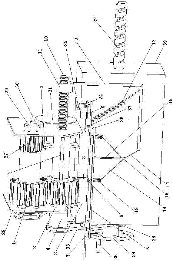
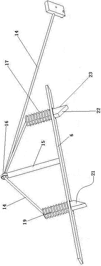
[0048] Such as Figure 1-3 As shown, a refitting mechanism that can automatically drill holes includes: a frame body 28, and a drive mechanism and a toggle mechanism installed on the frame body 28. The drive mechanism and the toggle mechanism are connected by a fork lever 8, and the drive mechanism is composed of Driven by the power unit, the drive mechanism drives the drill bit 32 to move,

[0049] - the drive mechanism can drive the drive gear 3 to rotate forward and reverse;

[0050] -The toggling mechanism includes a fixed plate 6 and a sliding lever 7. Two fork levers 8 are arranged on the lever 7. The two fork levers 8 are respectively...


PUM


Abstract

The invention relates to a refit mechanism capable of automatically drilling. The refit mechanism comprises a frame, a drive mechanism and a shifting mechanism, wherein the drive mechanism and the shifting mechanism are arranged on the frame and connected through shift fork rods. The drive mechanism is driven by a power device. The drive mechanism drives a drill bit to act, and the drive mechanism can drive a drive gear to rotate forwards and backwards. The shifting mechanism comprises a fixing plate and a shifting rod arranged in a sliding manner. The shifting rod is provided with the two shift fork rods which are located on the outer sides of the two ends of the drive gear respectively. The shifting rod is further provided with a stop lever. A screw rod is arranged at one end of a drive shaft. A thread sleeve connected with one end of a bent rod is connected to the screw rod in a sleeving manner through threads. The fixing plate is provided with two first stop mechanisms. A loop rod is arranged on the part, between the two first stop mechanisms, of the fixing plate. After a soft rope connected to the free end of the bent end passes a loop on the loop rod, the soft rope is divided into two strands to be connected with the two first stop mechanisms respectively. The two ends of a first spring are connected with the bent rod and the shifting rod respectively. The shifting rod is further provided with a protruding block in linkage with a manual stop mechanism.

Description

technical field [0001] The invention relates to a lathe tailstock, in particular to a refit mechanism capable of automatic drilling. Background technique [0002] Drilling on an ordinary lathe, the general method is to install the tapered shank of the drill in the tapered hole of the tailstock, fix the tailstock on the lathe guide rail, and then manually operate the hand wheel at the rear end of the tailstock to make the tailstock The seat cylinder advances along the axial direction of the drill bit to realize the translational feed of the drill bit; otherwise, the handwheel is reversed to make the tailstock cylinder retreat along the axial direction of the drill bit to realize the translational retraction of the drill bit. This method has high labor intensity and low labor efficiency for mass production of shaft holes, especially through holes. [0003] Therefore, for general drilling processing, especially large-scale through-hole processing, it is necessary to design a s...

Claims


Application Information

Patent Timeline
Patent Type & Authority Patents(China)
IPC IPC(8): B23B43/02B23B47/20B23B47/00
CPCB23B43/02B23B47/00B23Q5/40
Inventor 邵金发陶杰
Owner 宁波贝递同步带有限公司
Why Eureka
Try Eureka