Dry type transformer device with air inlet control valve

A dry-type transformer and control valve technology, applied in the field of transformers, can solve the problems of safe operation, overheating, equipment safety risks, etc., and achieve the effect of improving operation reliability, compact equipment structure, and reducing local overheating areas.

Inactive Publication Date: 2015-11-25
温岭市锦鹏日用品有限公司
View PDF4 Cites 0 Cited by
  • Summary
  • Abstract
  • Description
  • Claims
  • Application Information

AI Technical Summary

Problems solved by technology

However, there may be localized overheating in the individual winding columns of the transformer, w

Method used


Image

  • Dry type transformer device with air inlet control valve
  • Dry type transformer device with air inlet control valve
  • Dry type transformer device with air inlet control valve

Examples


Embodiment Construction

[0010] Combine below Figure 1-3 The present invention will be described in detail.

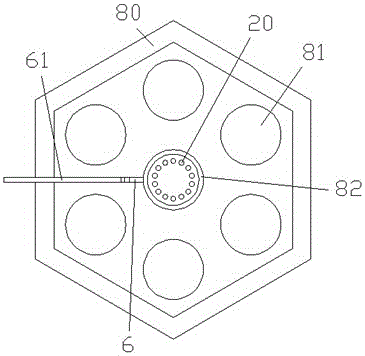
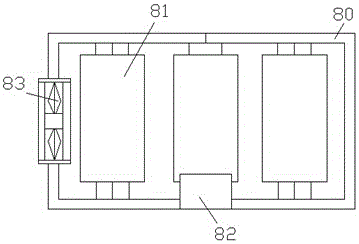
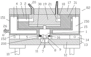
[0011] A dry-type transformer device with an air intake control valve according to an embodiment includes a casing 80 with a cooling exhaust fan 83 arranged on the side wall and a plurality of winding columns 81 arranged in the casing 80 uniformly in the circumferential direction, Wherein, the bottom of the central part surrounded by the plurality of winding columns 81 is provided with a cooling and blowing device 82 supplied with air from the gas delivery pipe 61, and the cooling and blowing device 82 includes a gas inlet nozzle 6 to communicate with the The air cavity annular shell 15 communicated with the gas conveying pipe 61, the inlet of the gas inlet nozzle 6 is provided with an air intake control valve 26 to control the air intake of the gas, and the air intake control valve 26 is an electromagnetic Control valve, the air cavity annular housing 15 is integrally provided with a bottom...


PUM


Abstract

A dry type transformer device with an air inlet control valve comprises a casing (80) and a plurality of winding columns (81), wherein the side wall of the casing (80) is provided with a cooling exhaust fan (83), and the winding columns (81) are arranged in the casing (80) and are evenly arranged in the circumferential direction. A cooling blowing device (82) for which air is supplied through a gas conveying pipe (61) is arranged at the bottom of the center part encircled by the winding columns (81). The cooling blowing device (82) comprises an air cavity annular casing (15) which is provided with a gas inlet pipe nozzle (6) so as to be communicated with the gas conveying pipe (61). An air inlet control valve (26) is arranged at the position of an inlet of the gas inlet pipe nozzle (6) so as to control the gas inlet amount. The air inlet control valve (26) is an electromagnetic control valve. A bottom surface annular part (152) and a drum-shaped part (151) on the upper side are integrally arranged on the air cavity annular casing (15), and the air cavity annular casing (15) is internally provided with a gas communicating cavity (150).

Description

technical field [0001] The application belongs to the field of transformers, in particular to a dry-type transformer device with an air intake control valve. Background technique [0002] Dry-type transformers often have multiple winding column assemblies to meet power needs. In some places where the installation environment is limited, these multiple winding columns can be arranged in a circular manner. However, the cooling ventilation in this arrangement requires a special design to meet the needs of cooling and ensure the safe operation of the equipment. [0003] The existing ventilation device quickly cools down the temperature of transformer components such as windings in the casing by setting a fan. However, there may be local overheating in the individual winding columns of the transformer, which has a particularly large impact on safe operation and poses a potential risk to the safety of the equipment. Contents of the invention [0004] The object of the present...

Claims


Application Information

Patent Timeline
IPC IPC(8): H01F27/08
Inventor 方达宏
Owner 温岭市锦鹏日用品有限公司
Why Eureka
Try Eureka