
A kind of electroplating Feiba swing pouring device

A technology of electroplating tank and swing frame, applied in the direction of electrolysis process and electrolysis components, to achieve the effect of reducing risks, reducing waste and ensuring the quality of electroplating

Active Publication Date: 2018-06-26
WUXI XINGYI INTELLIGENT ENVIRONMENT EQUIP CO LTD
View PDF8 Cites 0 Cited by
  • Summary
  • Abstract
  • Description
  • Claims
  • Application Information

AI Technical Summary

Problems solved by technology

[0004] The object of the present invention is to provide an electroplating flying bar swinging and pouring device, which has the characteristics of improving electroplating efficiency, ensuring electroplating quality and reducing the waste of chemical solution, so as to solve the above-mentioned problems existing in the electroplating process in the prior art

Method used


Image

  • A kind of electroplating Feiba swing pouring device
  • A kind of electroplating Feiba swing pouring device
  • A kind of electroplating Feiba swing pouring device

Examples


Embodiment 1

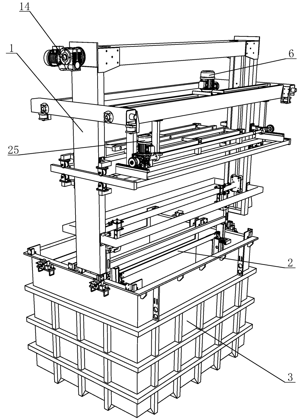
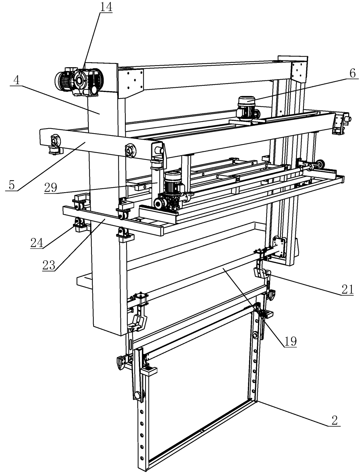
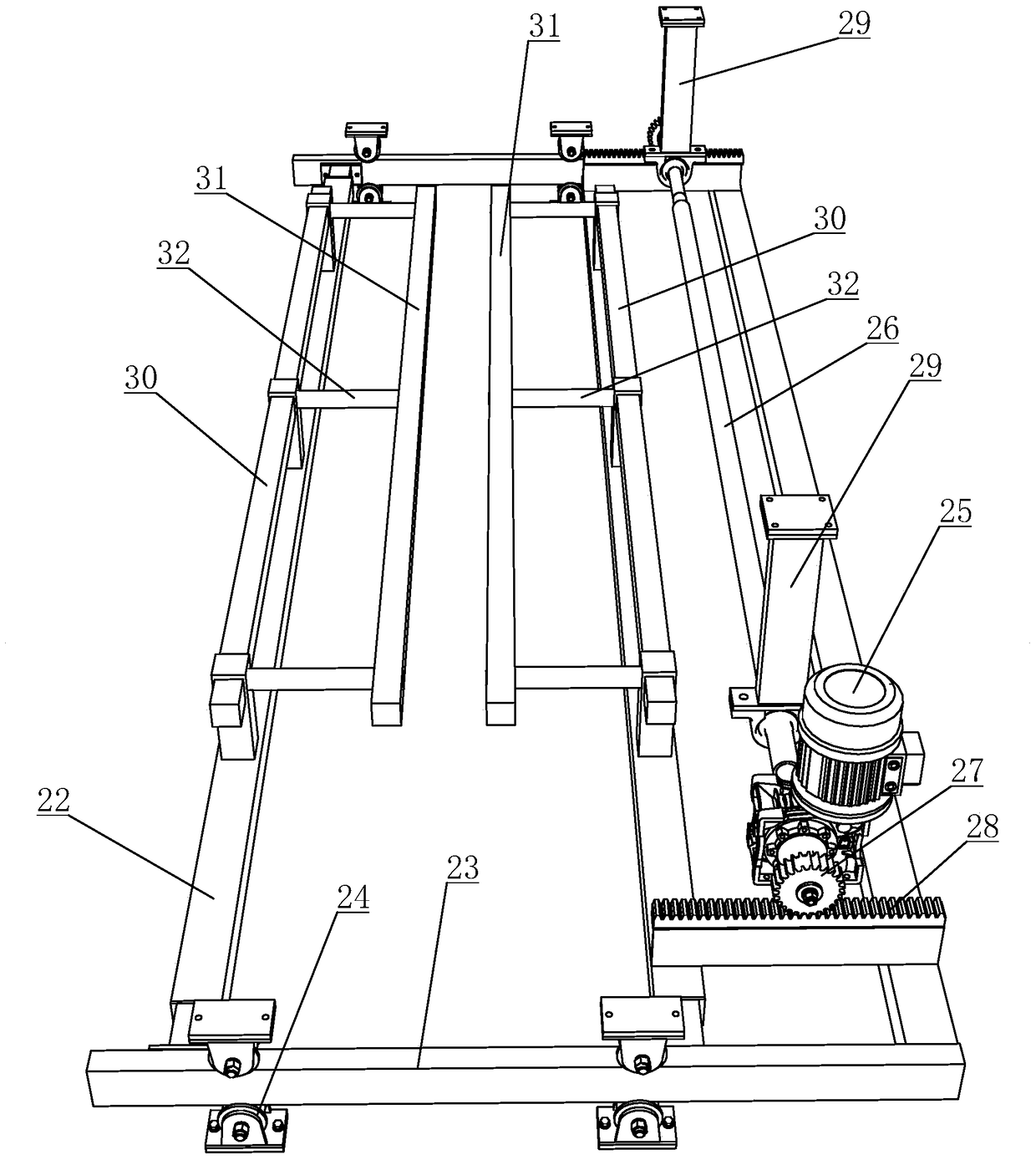
[0028] see Figure 1 to Figure 7 As shown, in this embodiment, a swinging and pouring device for an electroplating busbar includes an electroplating trolley 1, an electroplating busbar 2 and an electroplating tank body 3, the electroplating busbar 2 is arranged in the electroplating tank body 3, and the electroplating busbar 2 The electroplating crane 1 is arranged on the top of the electroplating tank body 3. The electroplating crane 1 includes a traveling frame 4 and a traveling device, a lifting device and a swing device arranged on the traveling frame 4. The traveling device includes a traveling frame 5 , walking motor 6, walking wheel box 7, walking driving wheel 8, driving gear 9, driving shaft 10, walking fixed rack 11, wheel 12 and walking guide rail 13, walking motor 6 drives walking driving shaft 10 to rotate, drives both sides The driving gear 9 in the walking wheel box 7 and the walking driving wheel 8 rotate. The driving guide rail 13 is fixedly installed on the ...

Embodiment 2

[0033] see Figure 8 and Figure 9 As shown, the main difference between this embodiment and Embodiment 1 is that the design of the swing reset device is different. In this embodiment, the swing reset device is arranged on the swing frame 22, and the two lances 31 are movably arranged on the swing frame 22. On the connecting rod 32, the connecting spring 42 is sleeved on the connecting rod 32. One end of the connecting spring 42 is fixed on the push rod 30, and the other end is fixedly connected to the ram 31. Both sides of the plate 34 are fixed with two swing limit rods 43 along the swing direction of the swing frame 35 . When the swing device is in operation, the swing frame 22 swings left and right as a whole, and the push rod 30 pushes the connecting spring 42, and then pushes the lance 31, bumps into the conductive rod 38, and makes the electroplating flybar 2 swing left and right. When swinging the device, the connection spring 42 returns to the initial state, and the...


PUM


Abstract

The invention discloses an electroplating conductive stick swinging and water-pouring device. The electroplating conductive stick swinging and water-pouring device comprises an electroplating special traveling crane, an electroplating conductive stick and an electroplating groove; the electroplating special traveling crane comprises a traveling crane rack, a traveling device, a hoisting device and a swinging device; the swinging device comprises a swinging frame; the swinging frame is provided with a driving device; two striking rods are arranged on the swinging frame at intervals; the electroplating conductive stick comprises two booms, two hoisting plates and a swinging rack; the two hoisting plates are fixedly connected with the two booms; the swinging rack is arranged between the two hoisting plates through a swinging bearing; a conductive rod is fixed on the top of the swinging rack; and after the electroplating conductive stick is hoisted by the hoisting device, the conductive rod is positioned between the two striking rods. By the electroplating conductive stick swinging and water-pouring device, workpieces can swing in the left-right direction; after the electroplating conductive stick swinging and water-pouring device is inclined at a certain angle, liquid taken out by the workpieces can pour to the groove within a short time, the electroplating efficiency is improved, electroplating quality is guaranteed, and waste of medicament solution is reduced.

Description

technical field [0001] The invention relates to electroplating equipment, in particular to a swinging and pouring device for an electroplating flybar. Background technique [0002] The electroplating process is the process in which electroplating workpieces are transferred between different tanks and each electroplating process is completed in sequence. Since the properties of the solution components in different tanks are different, during the transfer process of the electroplating workpiece, it is necessary to avoid the components of the bath solution in the previous tank being carried out by the workpiece and enter the next tank, which will eventually lead to cross-contamination of the solution. Affect the quality of electroplating, and cause the waste of electroplating solution. [0003] In the existing electroplating process, a certain time for dripping water or liquid is usually set after the workpiece leaves the tank, so as to facilitate the dripping of the carried o...

Claims


Application Information

Patent Timeline
Patent Type & Authority Patents(China)
IPC IPC(8): C25D17/08
Inventor 匡优新
Owner WUXI XINGYI INTELLIGENT ENVIRONMENT EQUIP CO LTD
Learn More