

Electroplating conductive stick swinging and water-pouring device
A technology of swinging device and electroplating tank, which is applied in the direction of electrolysis process and electrolysis components to ensure the quality of electroplating, prolong the discharge cycle of waste water and reduce waste.
- Summary
- Abstract
- Description
- Claims
- Application Information
AI Technical Summary
Problems solved by technology
Method used
Image

Examples
Embodiment 1
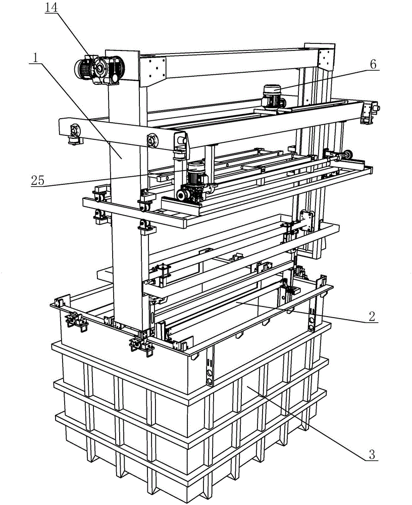
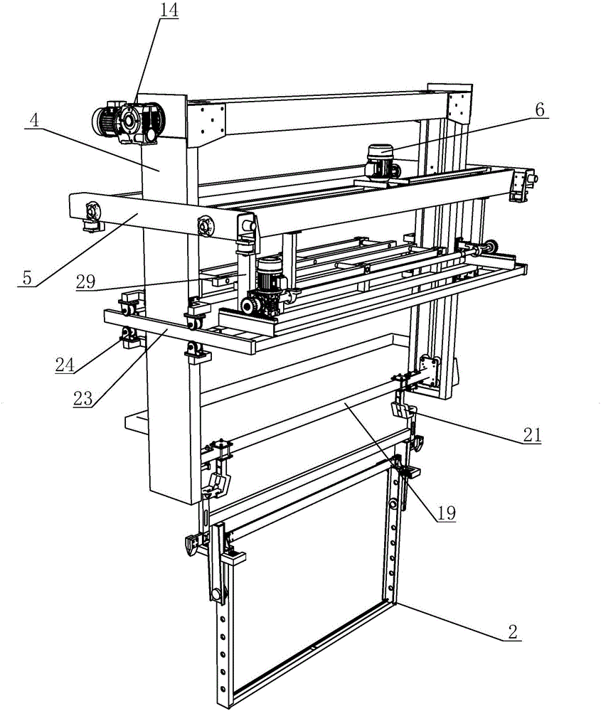
[0028] see Figure 1 to Figure 7 As shown, in this embodiment, a swinging and pouring device for an electroplating busbar includes an electroplating trolley 1, an electroplating busbar 2 and an electroplating tank body 3, the electroplating busbar 2 is arranged in the electroplating tank body 3, and the electroplating busbar 2 The electroplating crane 1 is arranged on the top of the electroplating tank body 3. The electroplating crane 1 includes a traveling frame 4 and a traveling device, a lifting device and a swing device arranged on the traveling frame 4. The traveling device includes a traveling frame 5 , walking motor 6, walking wheel box 7, walking driving wheel 8, driving gear 9, driving shaft 10, walking fixed rack 11, wheel 12 and walking guide rail 13, walking motor 6 drives walking driving shaft 10 to rotate, drives both sides The driving gear 9 in the walking wheel box 7 and the walking driving wheel 8 rotate. The driving guide rail 13 is fixedly installed on the ...
Embodiment 2
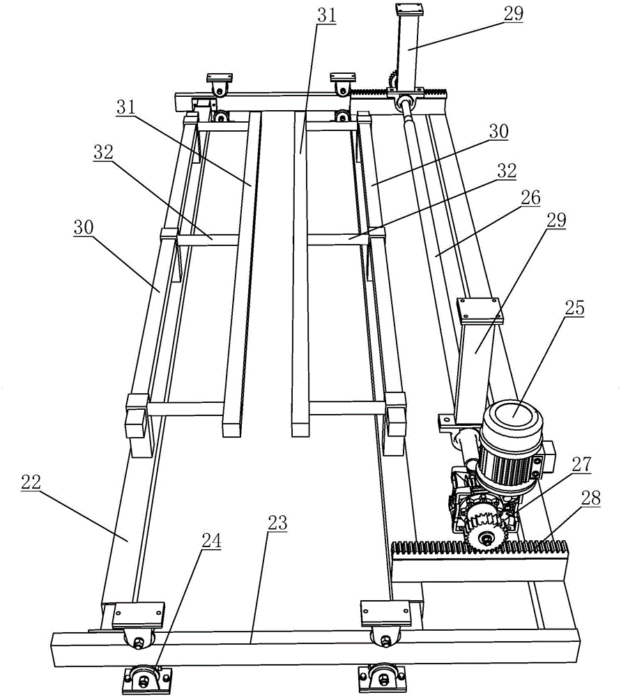
[0033] see Figure 8 and Figure 9 As shown, the main difference between this embodiment and Embodiment 1 is that the design of the swing reset device is different. In this embodiment, the swing reset device is arranged on the swing frame 22, and the two lances 31 are movably arranged on the swing frame 22. On the connecting rod 32, the connecting spring 42 is sleeved on the connecting rod 32. One end of the connecting spring 42 is fixed on the push rod 30, and the other end is fixedly connected to the ram 31. Both sides of the plate 34 are fixed with two swing limit rods 43 along the swing direction of the swing frame 35 . When the swing device is in operation, the swing frame 22 swings left and right as a whole, and the push rod 30 pushes the connecting spring 42, and then pushes the lance 31, bumps into the conductive rod 38, and makes the electroplating flybar 2 swing left and right. When swinging the device, the connection spring 42 returns to the initial state, and the...
PUM
 Abstract
Description
Claims
Application Information