Floating roller traction drive card type card-issuing machine suitable for cards of different thickness

A traction drive, floating roller technology, applied in instruments, ticketing equipment, etc., can solve the problems of small bite force between the roller and the card, can not float up and down, affecting work efficiency, etc., to achieve high card thickness compatibility, high friction, Simple to use effects

Active Publication Date: 2015-12-02
广东省高速公路有限公司 +1
View PDF7 Cites 4 Cited by
  • Summary
  • Abstract
  • Description
  • Claims
  • Application Information

AI Technical Summary

Problems solved by technology

[0004] However, the traction device in the existing card issuing machine adopts the upper and lower two rollers to pull and drive the card, and the rollers rotate to realize the traction of the card. It can only rotate around the axis and cannot float up and down. Therefore, the gap between the two rollers is fixed and cannot be suitable for cards of different thicknesses
[0005] At the same time, the existing traction device generally only has one set of rollers, and the bite force between the rollers and the card is relatively small, and the card is easy to slip, resulting in unstable card output
At the same time, when swiping stored-value cards and business cards, you need to put the card into the channel for reading, which greatly affects the work efficiency

Method used


Image

  • Floating roller traction drive card type card-issuing machine suitable for cards of different thickness
  • Floating roller traction drive card type card-issuing machine suitable for cards of different thickness
  • Floating roller traction drive card type card-issuing machine suitable for cards of different thickness

Examples


Embodiment Construction

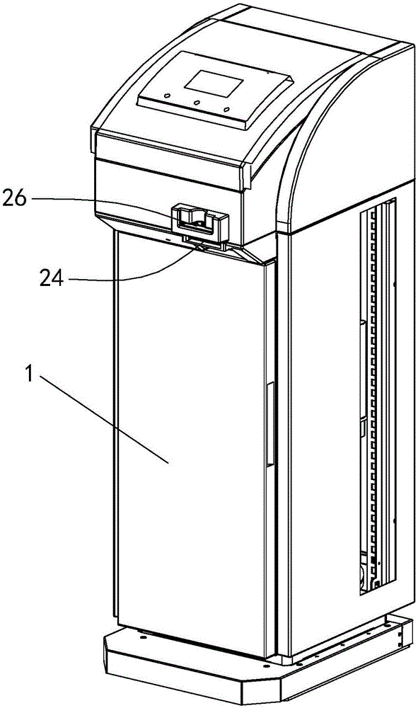
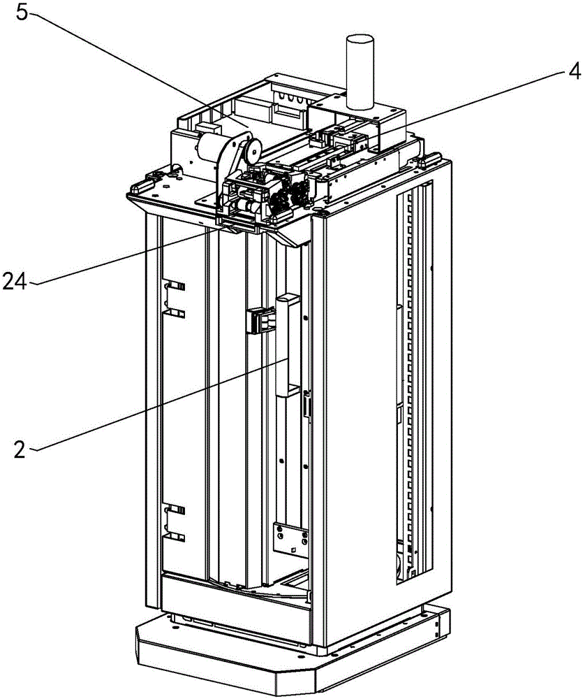
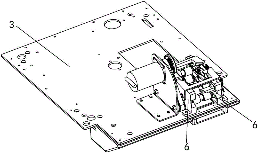
[0039] like Figure 1 to Figure 11The floating roller traction-driven card issuing machine suitable for cards of different thicknesses shown includes a casing 1, a card holder 2, an installation substrate 3, a traction device, a card issuance device 4, a driving device and a control device, and the installation substrate 3 has The hollow plate frame with openings, the installation substrate 3 is horizontally and fixedly arranged in the casing 1, and is located above the card holder 2, which is vertically arranged, and the card holder 2 has a card slot, a bayonet port, and a card cavity for storing cards And drive the card in the card cavity to move upwards from the card cavity card supporting mechanism, the traction device and the card issuing device 4 are all arranged on the installation substrate 3, the card issuing device 4 is adapted to the card slot of the card holder 2, and is used to The card in the card cavity is sent out, and the pulling device is adapted to the bayon...


PUM


Abstract

The invention discloses a floating roller traction drive card type card-issuing machine suitable for cards of different thickness. The machine comprises a chassis, a card holder, a mounting substrate, a traction device, a card-issuing device, a drive device and a control device. The mounting substrate is provided with a pair of traction bearing. The traction device comprises at least one traction mechanism. Each traction mechanism comprises a channel roller, a floating roller, a floating plate and a torsion spring, and the channel roller, the floating roller and the floating plate are arranged on the pair of the traction bearing. The channel rollers, the floating rollers and the floating plates are meshed through gear groups. Each channel roller is located below a floating roller. Each floating plate is hinged on a traction bearing. Each traction bearing is provided with a gap. Each floating roller is supported in a gap. The floating rollers and the floating plates are connected. A card-issuing channel is formed by a gap between a floating roller and a channel roller. Each torsion spring is arranged on a traction bearing. Each floating plate is pressed by the projecting end of a torsion spring. The card-issuing machine is capable of adjusting the gaps of the card-issuing channels, and is suitable for cards of different thickness.

Description

technical field [0001] The invention relates to a card machine, in particular to a floating roller traction-driven card issuing machine suitable for cards of different thicknesses. Background technique [0002] With the rapid development of science and technology, a large number of card transceivers are used in the management of vehicle traffic in expressways and residential areas. Due to the large thickness span of the access cards on the market, ranging from 0.9mm to 6mm, the channels of card transceivers currently on the market are generally The design is simple, and the compatibility with the thickness of the card is poor, and some product channels are designed to be compatible with the thickness of the card as a one-way wheel drive channel to suck the card, which is prone to problems such as card slipping and jamming. At the same time, when swiping business cards or stored value cards, It is necessary to put the card into the channel, swipe the card and then spit it out...

Claims


Application Information

Patent Timeline
Patent Type & Authority Applications(China)
IPC IPC(8): G07B15/06
Inventor 赖云峰林旭辉谭钜源郑伟生
Owner 广东省高速公路有限公司
Why Eureka
Try Eureka