
charging control method

A charge control method and a charger technology, which are applied in secondary battery charging/discharging, current collectors, electric vehicles, etc., can solve the problems that are not conducive to improving the charging speed, and achieve the effect of increasing the charging speed

Active Publication Date: 2017-04-19
深圳市华熹投资有限公司
View PDF4 Cites 0 Cited by
  • Summary
  • Abstract
  • Description
  • Claims
  • Application Information

AI Technical Summary

Problems solved by technology

Therefore, when designing, the maximum heat generation will be used to guide the design of the charging current, and this method is not conducive to improving the charging speed

Method used


Image

  • charging control method

Examples


Embodiment Construction

[0021] The present invention will be further described in detail below with reference to the drawings and embodiments.

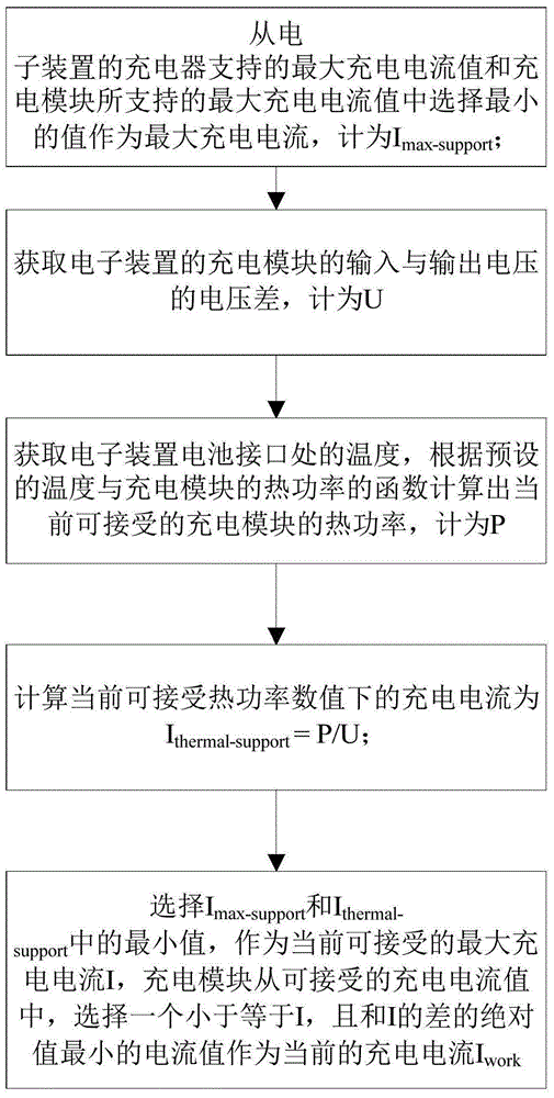
[0022] See figure 1 As shown, the charging control method of the present invention includes the following steps:

[0023] Step 1: According to the type of charger connected to the electronic device, from the maximum charging current value I supported by the corresponding charger type charger-support And the maximum charging current value I supported by the charging module of the electronic device max Choose the smallest value as the maximum charging current and count it as I max-support ;

[0024] Step 2: Obtain the voltage difference between the input and output voltages of the charging module of the electronic device and count it as U;

[0025] Step 3: Obtain the temperature at the battery interface of the electronic device, and calculate the currently acceptable thermal power of the charging module based on the function of the preset temperature and the therma...


PUM


Abstract

The invention discloses a charging control method. The method comprises: according to a type of a charger connecting an electronic device, a minimum value is selected from a maximum charging current value supported by the charger and a maximum charging current value supported by the charging module of the electronic device and is used as a maximum charging current Imax-support; a voltage difference U between an input voltage and an output voltage of the charging module is obtained; a temperature of a battery interface of the electronic device, and a charging module thermal power P that can be accepted currently is calculated according to a preset temperature and a thermal power function of the charging module; on the basis of the obtained thermal power P and voltage difference U, a charging current Ithermal-support under the currently acceptable thermal power value is calculated; and a minimum value between the Imax-support and the Ithermal-support is selected as a currently acceptable maximum charging current I, and the charging module selects a current value from the acceptable charging current values as a current charging current, wherein the selected current value is less than or equal to I and the absolute value of the difference between the selected current value and the I is the minimum one.

Description

Technical field [0001] The invention relates to a charging control method, in particular to a charging method that uses dynamic adjustment of the charging current to balance the relationship between the charging speed and the charging heating. Background technique [0002] Portable electronic devices, such as smart phones or tablet computers, are devices with limited size. The main heat dissipation method is passive heat dissipation. As the power provider of portable electronic devices, lithium batteries will become unstable at high temperatures. With the rapid improvement of the performance of portable electronic devices, the battery becomes insufficient, and timely, fast and safe charging becomes increasingly important. Generally, the charging method of lithium batteries is constant current charging-constant voltage charging. For linear charging circuits, this method generates a large amount of heat when the battery is under low voltage, and low heat when the battery is under h...

Claims


Application Information

Patent Timeline
Patent Type & Authority Patents(China)
IPC IPC(8): H02J7/00H01M10/44
CPCY02E60/10
Inventor 陈飞胡锦林付海望
Owner 深圳市华熹投资有限公司
Learn More