High precision on-line error compensation method for drift error of gyro with suspension rotor
A compensation method and technology for gyro drift, which can be applied to rotating gyroscopes, measuring devices, instruments, etc., and can solve the problems of insufficient samples, no analytical expression of compensation laws, and no universality.
- Summary
- Abstract
- Description
- Claims
- Application Information
AI Technical Summary
Problems solved by technology
Method used
Image
Examples
Embodiment Construction
[0130] specific implementation plan
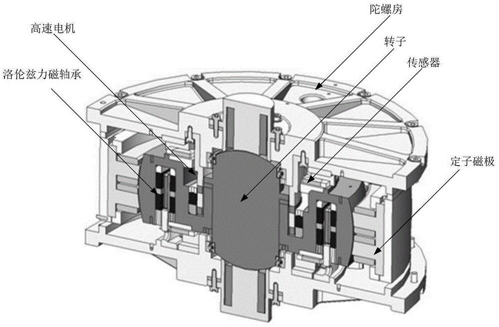
[0131] The implementation object of the present invention is as figure 1 As shown, the rotor of the magnetic levitation gyro is composed of two solid spherical segments with axial and radial radii r and R respectively, and R>r. Wherein, the outer edge of the spherical segment of the radial structure includes an annular groove for installing the Lorentz force magnetic bearing.
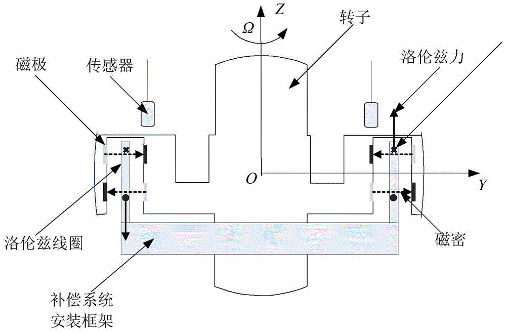
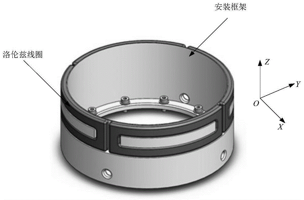
[0132] Lorentz force magnetic bearing error compensation system based on the principle of Ampere's law, the design principle diagram is as follows figure 2 As shown, the specific implementation steps are as follows:
[0133] (1) Disturbance moment modeling
[0134] A rotor coordinate system o-xyz that does not rotate with the rotor is established with the geometric center o of the maglev rotor as the origin, the rotor rotation axis is the z axis, and the x and y axes are located on the equatorial plane of the rotor and are perpendicular to each other.
[0135] ...
PUM
 Abstract
Description
Claims
Application Information
 - R&D
- Intellectual Property
- Life Sciences
- Materials
- Tech Scout
- Unparalleled Data Quality
- Higher Quality Content
- 60% Fewer Hallucinations
Browse by: Latest US Patents, China's latest patents, Technical Efficacy Thesaurus, Application Domain, Technology Topic, Popular Technical Reports.
© 2025 PatSnap. All rights reserved.Legal|Privacy policy|Modern Slavery Act Transparency Statement|Sitemap|About US| Contact US: help@patsnap.com


