
Quick density peak value clustering based polarimetric SAR image classification method

A density peak and classification method technology, applied in the field of target recognition, can solve the problems of poor classifier performance, inability to distinguish effectively, and poor maintenance of polarization scattering characteristics, etc., to achieve clear edges and good regional consistency Effect

Active Publication Date: 2015-12-09
XIDIAN UNIV
View PDF3 Cites 11 Cited by
  • Summary
  • Abstract
  • Description
  • Claims
  • Application Information

AI Technical Summary

Problems solved by technology

One of the shortcomings of H / α classification is that the division of regions is too arbitrary. When the data of the same class is distributed on the boundaries of two or more classes, the performance of the classifier will deteriorate. Another shortcoming is that when the data coexist in the same area When there are several different ground features, it will not be able to effectively distinguish
[0006] 2. Lee et al. proposed an unsupervised polarization SAR classification method based on H / α target decomposition and Wishart classifier, see LeeJS, GrunesMR, AinsworthTL, eta1.UnsupervisedclassificationusingpolarimetricdecompositionandthecomplexWishartclassifier[J].IEEETrans.Geosci.RemoteSensing.1999, 37( 5): 2249-2258. This method mainly uses the Wishart classifier to re-classify each pixel of the 8 categories after H / α division, thereby effectively improving the classification accuracy, but it cannot maintain all kinds of Insufficient polarization scattering properties of the

Method used


Image

  • Quick density peak value clustering based polarimetric SAR image classification method
  • Quick density peak value clustering based polarimetric SAR image classification method
  • Quick density peak value clustering based polarimetric SAR image classification method

Examples


Embodiment Construction

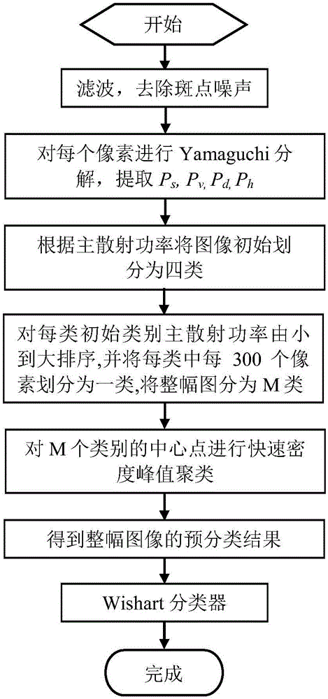
[0031] refer to figure 1 , the implementation steps of the present invention are as follows:

[0032] Step 1: filter the polarimetric SAR image to be classified, remove speckle noise, and obtain the filtered polarimetric SAR image.

[0033] The filtering of polarimetric SAR images usually adopts the existing refined polarimetric LEE filtering method, and the size of the filtering window is 7×7.

[0034] Step 2: Perform Yamaguchi decomposition on the coherence matrix T of each pixel in the filtered polarimetric SAR image to obtain the volume scattering power P of each pixel v , dihedral scattered power P d , surface scattering power P s and the helical scattering component P h .

[0035] Yamaguchi decomposition is a polarization target decomposition method. Different ground objects have different scattering characteristics. According to the scattering characteristics of different ground objects, this method decomposes the coherence matrix of each pixel into a linear combin...


PUM


Abstract

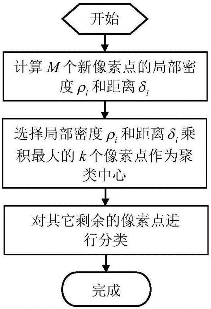
The present invention discloses a quick density peak value clustering based polarimetric SAR image classification method, mainly to solve the problem of low classification precision of an existing unsupervised polarimetric SAR classification method. The method comprises: 1. filtering an to-be-classified polarimetric SAR image; 2. performing Yamaguchi decomposition on the filtered polarimetric SAR image, and calculating four kinds of scattering power of each pixel point; 3. extracting main scattering power of each pixel point, and initially dividing the whole image into four classifications; 4. according to the main scattering power of all pixel points in an initial classification, dividing the whole polarimetric SAR image into M classifications; 5. using center points of the M classifications as new pixel points for clustering, and converting a clustering result into a pre-classification result of the whole image; and 6. performing iterative classification on the pre-classification result to obtain a final classification result. The experiment shows that the method provided by the prevent invention has a better classification effect, and can be used to perform unsupervised classification on various polarimetric SAR images.

Description

technical field [0001] The invention belongs to the technical field of image processing, relates to a polarimetric SAR image classification method, and can be used for target recognition. Background technique [0002] With the development of remote sensing technology in the fields of satellites, manned spaceflight, and lunar exploration projects, polarimetric SAR has become the development trend of SAR, and polarimetric SAR can obtain more abundant target information. Hydrology and oceanography have a wide range of research and application values, such as topographic mapping, resource exploration, disaster monitoring and astronomical research and other fields. The purpose of polarimetric image classification is to determine the class to which each pixel belongs, using polarimetric data obtained from airborne or spaceborne polarimetric sensors. In recent years, the classification using polarimetric SAR measurement data has been highly valued in the field of international rem...

Claims


Application Information

Patent Timeline
IPC IPC(8): G06K9/00G06K9/62
CPCG06V20/13G06F18/23213G06F18/217
Inventor 滑文强王爽焦李成岳波熊涛郭岩河马晶晶
Owner XIDIAN UNIV
Learn More