
Adjustment mechanism for adjusting jaws of shear

A technology of adjusting mechanism and shearing machine, which is applied to cutters, shearing devices, earthmoving machines/shovels and other directions for shearing machine devices, and can solve the problems of cost, redundancy and cumbersomeness.

Active Publication Date: 2015-12-09
CATERPILLAR INC
View PDF6 Cites 2 Cited by
  • Summary
  • Abstract
  • Description
  • Claims
  • Application Information

AI Technical Summary

Problems solved by technology

However, completely replacing the board may require an operator to remove the jaws and reinsert a new board
Further, additional costs are incurred through shearer replacement and downtime
Also, this method can be lengthy and cumbersome, while also requiring expensive tools to pivotally loosen and refasten the jaws from each other

Method used


Image

  • Adjustment mechanism for adjusting jaws of shear
  • Adjustment mechanism for adjusting jaws of shear
  • Adjustment mechanism for adjusting jaws of shear

Examples


Embodiment Construction

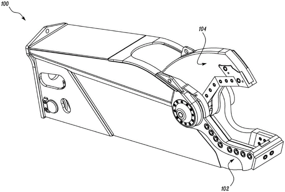
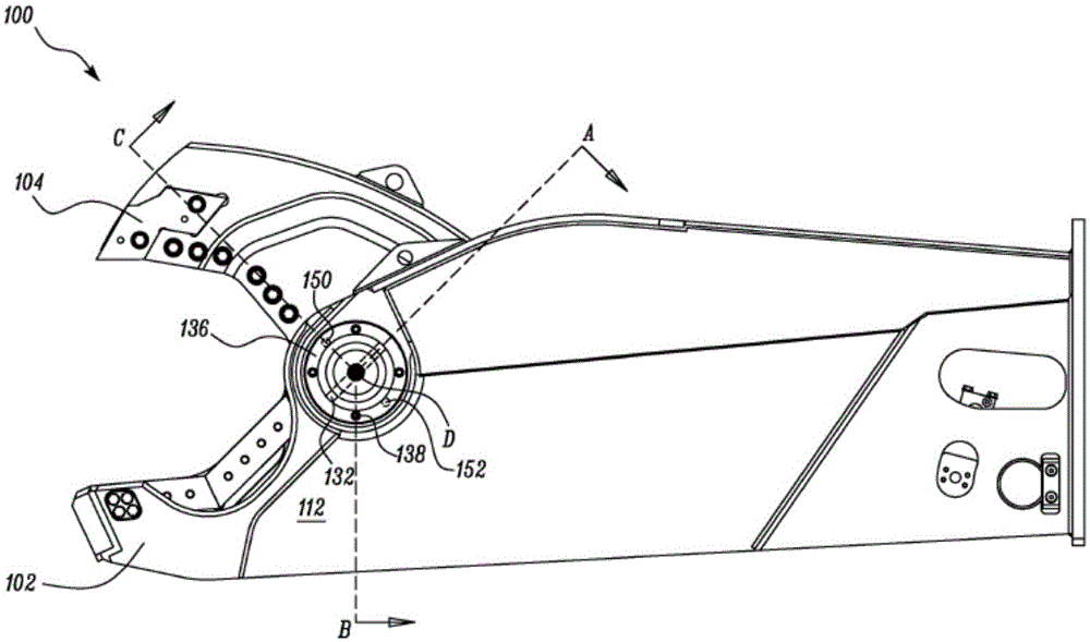
[0013] The invention relates to an adjustment mechanism for adjusting the jaws of a shearing machine. figure 1 A front perspective view of a shear 100 according to an exemplary embodiment of the present invention is shown. In one embodiment, the shearer 100 may be a shearer of the type commonly used for heavy construction machinery to shear rare earth materials, lumber, or building materials. In one embodiment, shearer 100 may be a hydraulic shearer configured to be hydraulically powered using brakes and trunnion linkages. In another embodiment, shearer 100 may be an electric shearer. Although the description focuses on hydraulic shears, it is understood that the apparatus and method can be similarly applied to other types of shears 100 .

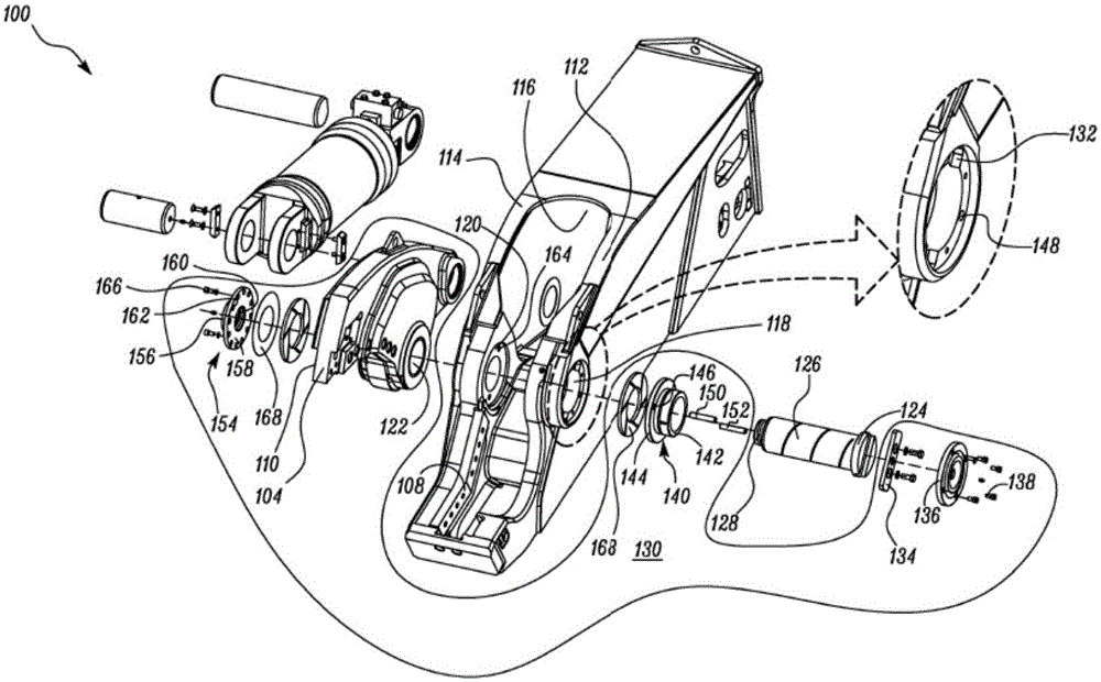
[0014] figure 2 An exploded view of hydraulic shear 100 is shown. The hydraulic shear 100 includes a first jaw 102 , a second jaw 104 and a pivot pin 106 . in such as figure 2 In one embodiment shown, the first jaw 102 is a stationa...


PUM


Abstract

A hydraulic shear including a first jaw, a second jaw, a pivot pin, and an adjustment mechanism is provided. The first jaw includes a first and second sidewall defining a first and second opening therethrough. The second jaw is disposed between the first and second sidewalls and includes a third opening. The pivot pin extends through the first, second, and third openings to pivotally connect the first and second jaws. The adjustment mechanism is coupled to the first jaw, the second jaw, and the pivot pin. The adjustment mechanism slidably adjusts a position of the second jaw on the pivot pin with respect to first and second sidewalls of the first jaw.

Description

technical field [0001] The present invention relates to a shear, such as a hydraulic shear, and more particularly to an adjustment mechanism for adjusting the jaws of a shear. Background technique [0002] Shears employed on heavy construction machinery include a pair of jaws with one or more blades positioned thereon. The jaws may include pivoting jaws and fixed jaws. The jaws may be mounted on a pivot pin such that one of the jaws may pivot relative to a fixed jaw therein. The pivoting jaws move the associated blades relative to the blades on the fixed jaws to provide shearing and crushing forces to the object. Such shears may further employ shim plates and low friction plates mounted on pivot pins and positioned adjacent each of the jaws. The shim plate is configured to maintain a predetermined amount of tolerance between the jaws while the low friction plate serves to reduce friction between the jaws during operation. [0003] During the operation of the shearing mac...

Claims


Application Information

Patent Timeline
Patent Type & Authority Applications(China)
IPC IPC(8): B23D17/00B23D35/00
CPCE02F3/965B23D17/00B23D35/005E02F9/006
Inventor J·K·克莱蒙斯
Owner CATERPILLAR INC
Features
  • Generate Ideas
  • Intellectual Property
  • Life Sciences
  • Materials
  • Tech Scout
  • Unparalleled Data Quality
  • Higher Quality Content
  • 60% Fewer Hallucinations
Learn More