Flow control valve and hydraulic system
A technology of flow regulating valve and spool, which is applied in the direction of fluid pressure actuating device, lift valve, valve details, etc., and can solve the problems such as stuck flow regulating valve spool
- Summary
- Abstract
- Description
- Claims
- Application Information
AI Technical Summary
Problems solved by technology
Method used
Image

Examples
Embodiment 1
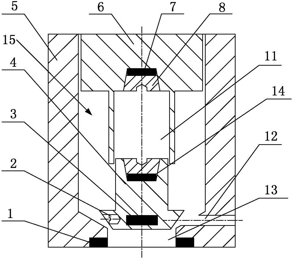
[0065] see figure 1 , the oil pump flow regulating valve has the performance of preventing the spool 4 from being stuck and running stably for a long time. The flow regulating valve of the oil pump includes: a first magnet 1, a set screw, a second magnet 3, a valve core 4, a valve body 5, a slider 6, a third magnet 14, a fourth magnet 7, a plug 8, and a pressing block 9 , Chute 11, bypass hole 12, oil inlet hole 13.
[0066] Plug 8 is that the outer surface is a taper thread, and its fixing is realized by threaded connection.
[0067] A fixing groove for fixing the first magnet 1 is opened at the bottom of the oil inlet hole 13 . The arrangement of the first magnet 1 can be circular, see Figure 4 ; or circular, square evenly distributed, see Figure 5 .
[0068] The slider 6 is circular, and the slider 6 has three structural forms: the first form is as figure 1 As shown, the latter two are as figure 2 and image 3 , which will be described in detail later. The slide...
Embodiment 2
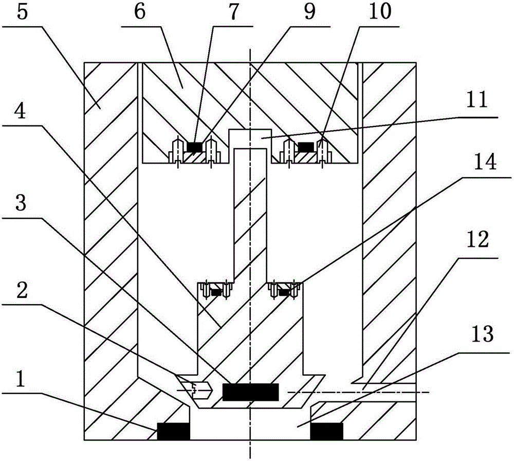
[0073] see figure 2 , in this embodiment the slider and figure 1 The sliders shown are constructed differently. see figure 2 , In this embodiment, a cylindrical chute 11 with a certain depth and a certain diameter is opened upward from the lower end of the slider 6 . This chute 11 size is determined by the slide bar size on the spool 4. The lower end of the slide block 6 is provided with a ring hole at 7 mm to 10 mm upwards, and the fourth magnet 7 is installed in the ring hole at the lower end of the slide block 6 and is fixed by a pressing block 9 and a set screw 10.
[0074] see figure 2 , in this embodiment, the spool 4 is installed in the following manner: a slender rod protrudes from the top of the straight rod of the spool 4 as a slide rod, the diameter of the slide rod of the spool 4 is 4mm-10mm smaller than the diameter of the main body of the spool 4, and the slide rod The length is determined by the stroke of the spool 4. The top of the main body of the spo...
Embodiment 3
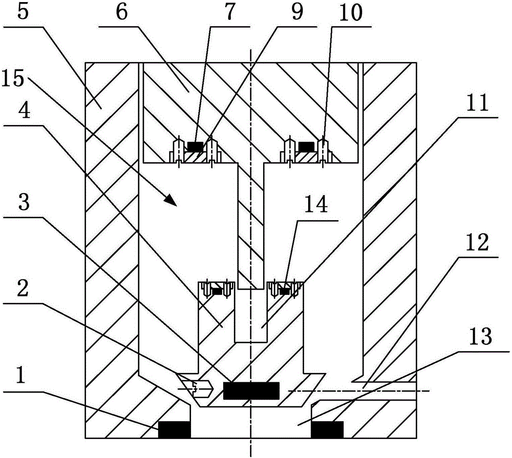
[0077] see image 3 , the slider in this embodiment is the same as that of the above embodiment figure 1 , figure 2 The sliders shown are constructed differently. In this embodiment, a section of slender rod protrudes from the lower end of the slider 6 as a slider. The slide bar is cylindrical, and the size of the slide bar is determined by the chute 11 on the spool 4 . The lower end of the slide block 6 has an annular hole at 8 mm to 13 mm upwards, and the fourth magnet 7 is installed in the annular hole at the lower end of the slide block 6 and is fixed by a pressing block 9 and a set screw 10.
[0078] In this embodiment, the valve core 4 is installed in the following way: the top of the straight rod of the valve core 4 has a cylindrical chute with a depth of 7 mm to 9 mm downward, and the top of the straight rod of the valve core 4 has a circular hole with a depth of 7 mm to 10 mm downward. , the second magnet 3 is built into the ring hole and fixed by the set screw 2...
PUM
 Abstract
Description
Claims
Application Information
 - R&D
- Intellectual Property
- Life Sciences
- Materials
- Tech Scout
- Unparalleled Data Quality
- Higher Quality Content
- 60% Fewer Hallucinations
Browse by: Latest US Patents, China's latest patents, Technical Efficacy Thesaurus, Application Domain, Technology Topic, Popular Technical Reports.
© 2025 PatSnap. All rights reserved.Legal|Privacy policy|Modern Slavery Act Transparency Statement|Sitemap|About US| Contact US: help@patsnap.com