A combined positioning device and positioning method

A technology combining positioning and positioning methods, applied in the direction of measuring devices, instruments, etc., can solve the problems of distortion of extracted elements, unreasonable installation of probes, deterioration of measurement accuracy, etc., to improve measurement accuracy, shorten installation, adjustment and alignment time, The effect of reducing human measurement error

Inactive Publication Date: 2017-08-25
XI'AN INST OF OPTICS & FINE MECHANICS - CHINESE ACAD OF SCI
View PDF8 Cites 0 Cited by
  • Summary
  • Abstract
  • Description
  • Claims
  • Application Information

AI Technical Summary

Problems solved by technology

If the workpiece to be measured is directly placed on the workbench, the extracted elements may be distorted because the measurement positioning end face is not perpendicular to the central axis, such as figure 1 shown
[0005] We are using a ZEISS CONTURA G2 three-dimensional coordinate measuring machine now. Since the probe base and the extension connecting rod are connected by threads, when installing the star probe assembly, the existing method is to look down from the top of the magnetic chuck. Depending on whether the axis of the probe seat coincides with the axis of the positioning groove, this method is likely to cause misjudgment, making the axis of the probe seat not parallel to the X-axis or Y-axis of the three-coordinate measuring machine, resulting in distortion of the extracted elements and measurement errors, such as image 3 , Figure 4 shown
It can be seen that when using three coordinates to measure roundness and coaxiality errors, if the installation of the workpiece and the probe is unreasonable, it will introduce other geometric errors into the measurement process, making the measurement accuracy worse.

Method used


Image

  • A combined positioning device and positioning method
  • A combined positioning device and positioning method
  • A combined positioning device and positioning method

Examples


Embodiment Construction

[0054] The present invention is described in further detail below in conjunction with accompanying drawing:

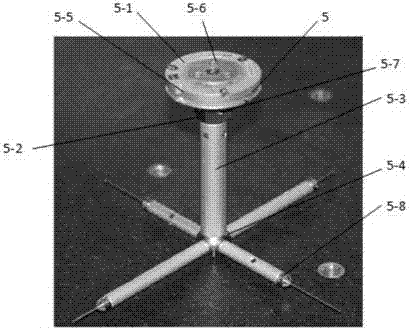
[0055] see Figure 5 to Figure 10 , the present invention provides a combined positioning device, including a base plate 1-1 and a support portion; a first guide rail 1-2 is arranged on the base plate, the first guide rail is parallel to the base plate, and a first slider 1-3 is arranged on the first guide rail and the second slide block 1-4, the first slide block and the second slide block can slide along the axial direction of the first guide rail, the first slide block and the second slide block are respectively provided with the first pointer type dial gauge 1 -5 and the second pointer dial gauge 1-6, the heads of the first pointer dial gauge 1-5 and the second pointer dial gauge 1-6 are all used to contact the datum surface of the measured workpiece; Move the first horizontal slider 1-3 and the second horizontal slider 1-4 horizontally according to the reference ...


PUM


Abstract

The invention provides a combined positioning device and a positioning method. The combined positioning device comprises a bottom plate and a supporting part; the bottom plate is provided with a first guide rail; the first guide rail is parallel to a bottom plate; the first guide rail is provided with a first sliding block and a second sliding block; the first sliding block and the second sliding block are respectively provided with a first pointer-type dial indicator and a second pointer-type dial indicator; the supporting part comprises a transverse section and a vertical section; the transverse section is fixedly connected with the bottom plate; the vertical section is vertical with the bottom plate; the transverse section is provided with a positioning hole; the positioning hole is used for mounting a probe seat of a probe assembly; the vertical section is provided with a second guide rail; the second guide rail is vertical with the first guide rail; a third sliding block is arranged on the second guide rail; a positioning head is arranged on the third sliding block; the positioning head is parallel to the transverse part; and the positioning head is used for being limited at the center of a magnetic sucker positioning groove of the probe assembly. The combined positioning device and the positioning method have the advantages that the structure is simple, the positioning method is quick, artificial measurement errors are reduced, and the measurement efficiency and the application range of a three-coordinate measurement machine are further improved.

Description

technical field [0001] The invention relates to the technical field of precision testing, in particular to a combined positioning device and a positioning method. Background technique [0002] With the rapid development of mechatronics technology and computer technology, three-coordinate measuring machines have gradually approached the production site, especially in the working environment of precision manufacturing and mass inspection, and are widely used in precision machinery, electronics, instruments and other fields. The three-coordinate measuring machine is one of the most effective methods for measuring and obtaining dimensional data. It can replace a variety of measuring tools, with high measurement accuracy and good repeatability. [0003] The probe base assembly 5 of the coordinate measuring machine, such as figure 2 , including probe base 5-4, connecting rod 5-3, probe 5-8, magnetic chuck 5-1 and magnetic chuck base 5-2, the lower end of the connecting rod is con...

Claims


Application Information

Patent Timeline
Patent Type & Authority Patents(China)
IPC IPC(8): G01B21/00G01B21/20G01B21/24
Inventor 付西红李华马娜娜周美英陈生辉杜延平
Owner XI'AN INST OF OPTICS & FINE MECHANICS - CHINESE ACAD OF SCI
Why Eureka
Try Eureka