
Locomotive head lamp

A technology of headlights and locomotives, applied in the field of lighting systems, can solve problems such as fuel waste and high additional loads

Active Publication Date: 2015-12-23
丹·梅塞 +1
View PDF7 Cites 0 Cited by
  • Summary
  • Abstract
  • Description
  • Claims
  • Application Information

AI Technical Summary

Problems solved by technology

In addition, the existing headlights have a high additional load, which will cause waste of fuel

Method used


Image

  • Locomotive head lamp
  • Locomotive head lamp
  • Locomotive head lamp

Examples


Embodiment Construction

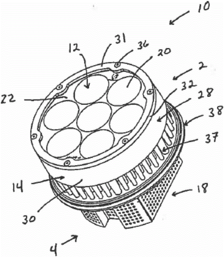
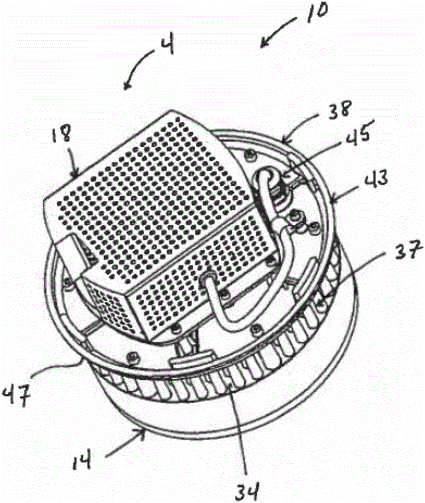
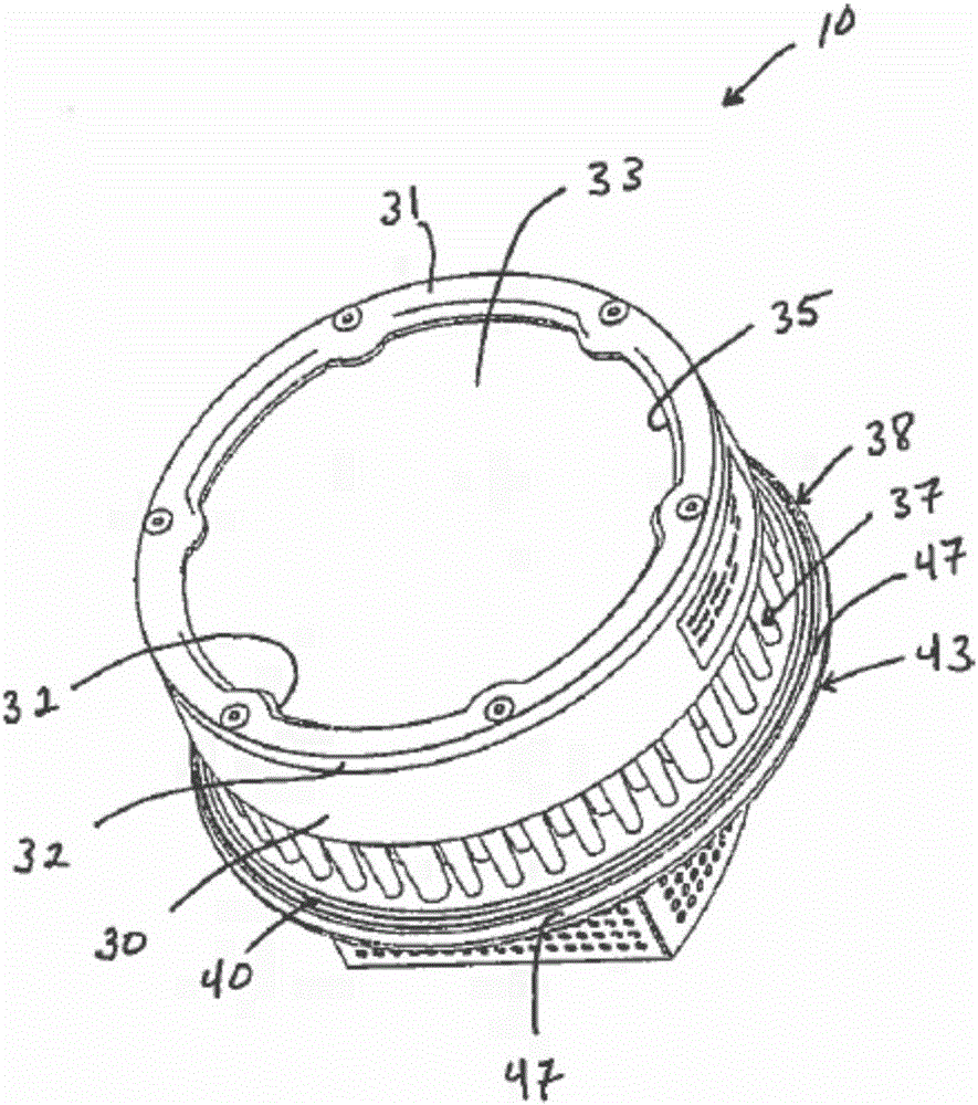
[0022] The motorcycle headlight disclosed by the present invention is specially designed to optimize the heat generated by the light source of the headlight. In an exemplary embodiment, the headlight includes an upper portion and a lower portion.

[0023] The lower part includes at least a part of electronic devices and / or circuits required to start the light source when the headlight is installed in the motorcycle headlight housing, and a lower housing for placing the electronic devices and / or circuits.

[0024] The upper part includes a light source, an upper shell for placing the light source, multiple fins and a base. The light source preferably includes one or more LED bulbs. The use of one or more LED bulbs has been shown to reduce locomotive parasitic loads by up to around 86%, resulting in significant savings in fuel costs. In addition, LED bulbs require less maintenance than conventional halogen bulbs, and the lifespan of said motorcycle headlights is approximately ...


PUM


Abstract

A locomotive head lamp comprises one or more light emitting diode (LED) bulbs. By adopting the head lamp, about 86% of additional loads of a locomotive can be reduced. The head lamp is mounted in a head lamp shade of the locomotive so that heat produced by the LED bulbs can prevent ice and snow around the locomotive head lamp from staying, and electronic devices or circuits connected to a locomotive power supply and used for starting the LED bulbs can be protected against damage.

Description

technical field [0001] The present invention relates generally to lighting systems, and more particularly to a motorcycle headlight. Background technique [0002] There are many disadvantages in traditional motorcycle headlights. One of the disadvantages is that conventional motorcycle headlights are embedded in the motorcycle's headlight housing. The concave part is likely to cause ice and snow to accumulate between the front edge of the headlight and the wall of the headlight cover of the motorcycle. [0003] There is also a disadvantage of the traditional halogen headlights. When the headlights are used on the locomotive, the temperature can be as high as 140°C, which has the danger of burning. [0004] In addition, conventional light-emitting diode (“LED”) headlights for motorcycles can generate heat and damage electronic devices and circuits inside the LED headlights depending on where the LED headlights are embedded in the motorcycle headlight housing. In addition, ...

Claims


Application Information

Patent Timeline
IPC IPC(8): F21S8/10F21V31/00F21V29/10F21V29/74F21V15/02F21V21/00F21W101/02F21Y101/02F21W107/10
Inventor 丹·梅塞乔·唐南
Owner 丹·梅塞
Learn More