
Spiral Hybrid Stent

A helical, main stent technology, applied in the field of stents

Inactive Publication Date: 2017-09-22
MEDINOL LTD
View PDF24 Cites 0 Cited by
  • Summary
  • Abstract
  • Description
  • Claims
  • Application Information

AI Technical Summary

Problems solved by technology

[0007] Another problem that arises in the field is the ability to produce stents with uniformly high flexibility and adequate radial support when trying to simplify the stent manufacturing process to reduce costs but still prevent manufacturing defects

Method used


Image

  • Spiral Hybrid Stent
  • Spiral Hybrid Stent
  • Spiral Hybrid Stent

Examples


Embodiment Construction

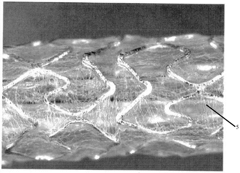
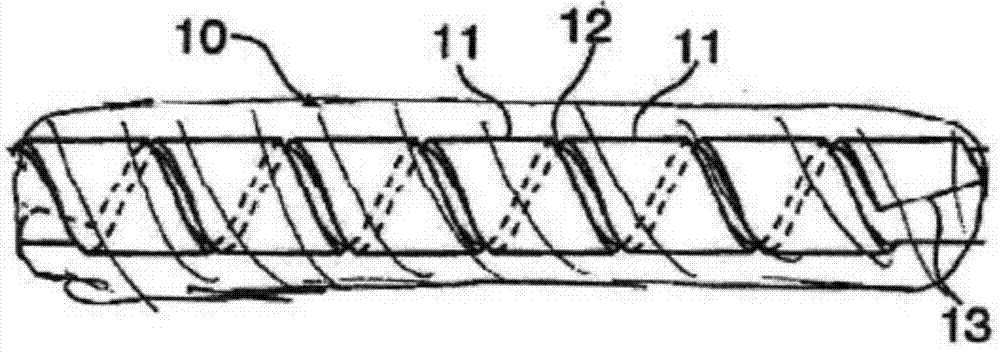
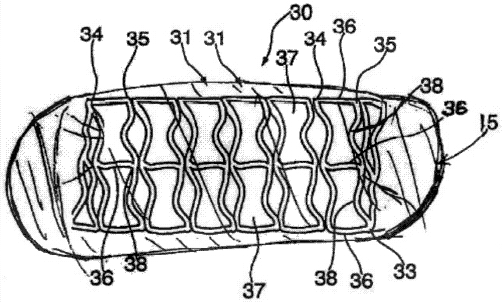
[0035] The present invention provides a new class of endoluminal prosthetic devices defined as helical hybrid stents. In particular, the stents of the present invention comprise a main stent component in the form of a helical tubular structure. The main stent component may be held in its coiled position by a second component that secures the helical coil into the tubular structure. The second component may be one or more of various means of securing the main stent component in tubular form. The second component may for example be a weld, an interlock and / or a polymer. In one embodiment, the second component comprises a polymer or polymer fibers wrapped around or embedded within the coiled main stent component. The elastic range of the polymer fiber layer must be sufficient to allow expansion and maximum bending of the stent during and after implantation without reaching the elastic limit.

[0036] The stents of the invention may be balloon expandable or self-expanding, or f...


PUM


Abstract

An expandable helical stent with anchors is provided. The stent is formed from flat or tubular metal into a helically wound structure with an undulating pattern. The main stent component may be formed from a single helically wound component. Alternatively, multiple helically wound strips may be used to form scaffolds that vary in design, material, or other characteristics. The helical tubular structure may be secured with fasteners such as welds, interlocks or polymers to maintain the tubular configuration of the helical coils. The helical coils of the main stent component may be spaced apart from or seated to each other. The seating of the undulations of adjacent helical coils helps to maintain the tubular shape of the helically wound stent. Additionally, this seating of the helical coil prevents the polymer layer from sagging at any point between cycles of the helical coil.

Description

technical field [0001] The present invention relates generally to stents, which are intraluminal implants implanted in a vessel (e.g., blood vessel) in the body to support the vessel and keep the vessel open or to secure or support other endoprostheses within the vessel. prosthetic device. Background technique [0002] Various scaffolds are known in the art. Typically, stents have a generally tubular shape and are expandable from a relatively small unexpanded diameter to a larger expanded diameter. For implantation, a stent is typically mounted on the end of a catheter, wherein the stent remains on the catheter in its small to relatively small unexpanded diameter. Using the catheter, the unexpanded stent is guided through the lumen to the desired implantation site. Once the stent is at the intended implantation site, the stent can be removed either by internal forces (e.g., by inflating a balloon inside the stent) or by allowing the stent to self-expand (e.g., by removing...

Claims


Application Information

Patent Timeline
Patent Type & Authority Patents(China)
IPC IPC(8): A61F2/88A61F2/91
CPCA61F2/88A61F2/91A61F2220/0058A61F2230/0091A61F2220/0083
Inventor 雅各布·里克特奥列格·魏茨曼伊戈尔·别洛布罗夫
Owner MEDINOL LTD
Learn More