
Systems and methods to reinforce excavation walls

a technology of reinforcement and excavation walls, applied in excavations, construction, foundation engineering, etc., can solve the problems of increased cost, laborious, and reinforcing techniques, and achieve the effects of improving the load-carrying capacity of the soldier pile wall, enhancing the elastic range of the soldier pile material, and improving the fatigue li

Active Publication Date: 2017-06-20
POST TENSIONING SOLUTIONS
View PDF12 Cites 0 Cited by
  • Summary
  • Abstract
  • Description
  • Claims
  • Application Information

AI Technical Summary

Benefits of technology

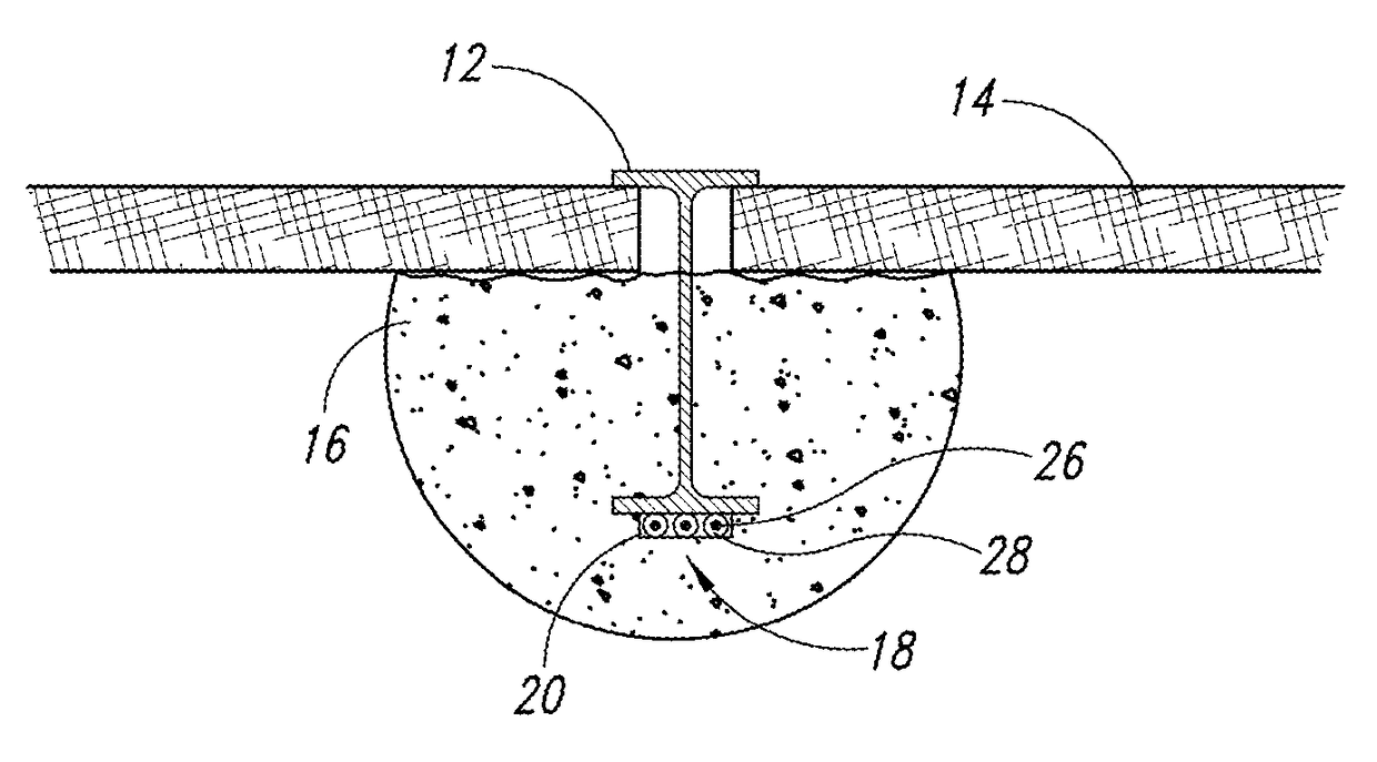
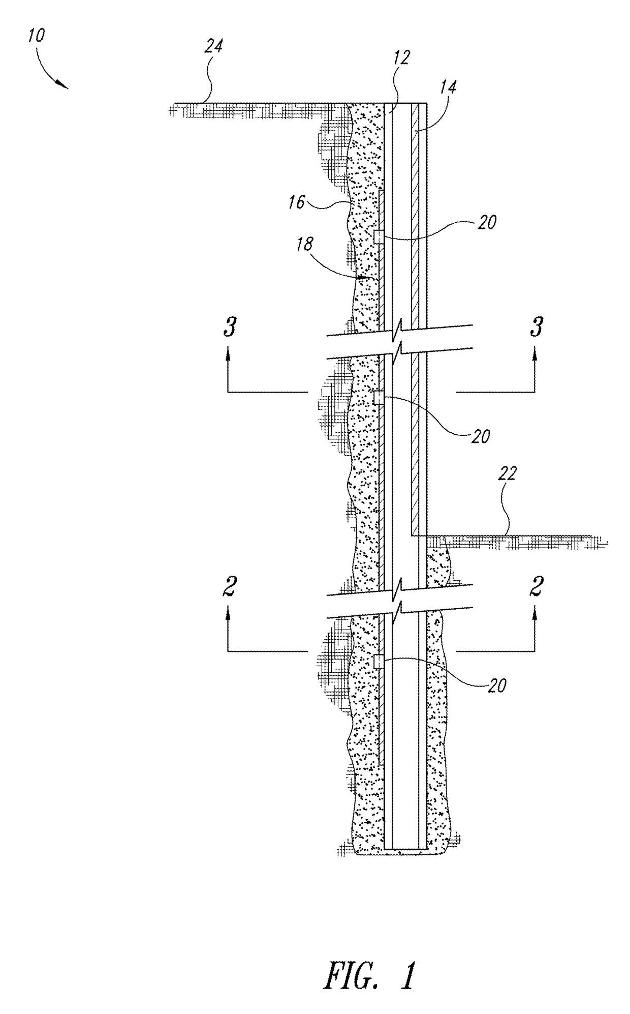
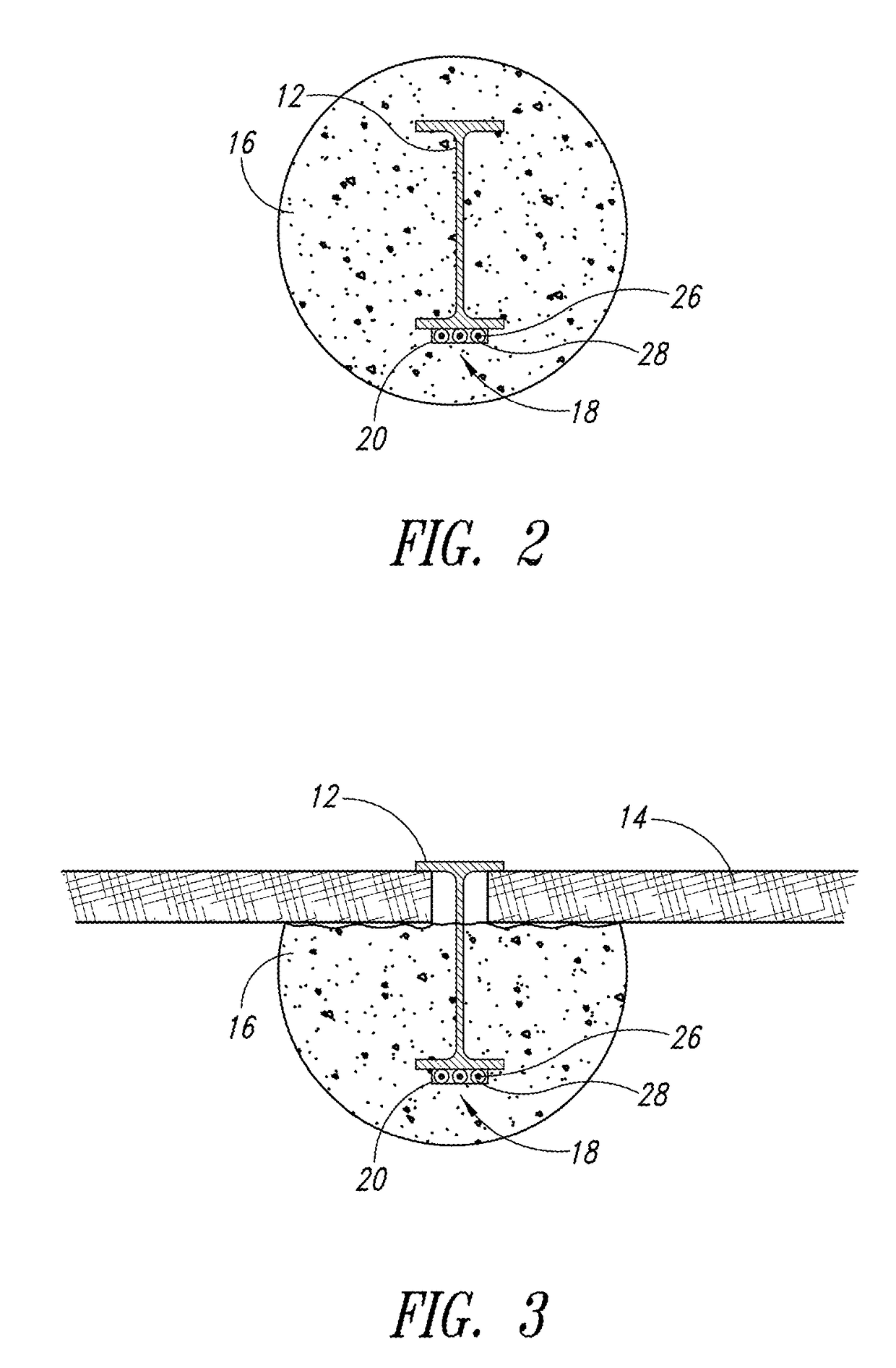
[0007]Embodiments described herein provide soldier pile walls, systems, and methods that are well-adapted to shore excavation sites using lighter and more slender soldier piles, improve the fatigue life, enhance the elastic range of the soldier pile material, and improve load-carrying capability of the soldier pile walls, among other advantages and benefits. According to one embodiment, a soldier pile for shoring an excavation site may be summarized as including a plurality of drilled shafts drilled along an edge of the excavation site; a plurality of soldier piles, with each of the plurality of soldier piles being positioned within a respective drilled shaft; and a pre-stressing system coupled to at least some of the plurality of soldier piles. The pre-stressing system may be configured to induce stresses to counteract working stresses of the soldier pile wall.
[0008]According to another embodiment, a system for shoring an excavation site having a plurality of adjacent holes drilled along an edge of the excavation site where a soldier pile wall is to be erected may be summarized as including a plurality of modular soldier piles, each of the plurality of modular soldier piles to be positioned within a respective hole and including a pre-stressing system coupled thereto. The pre-stressing system may have a post-tensioning strand enclosed in a protective cover, with the protective cover having grout therein to surround and enclose the post-tensioning strand; an anchorage system positioned at each end of the post-tensioning strand and coupled to a respective end of the post-tensioning strand; and a compressive flange brace having an aperture to allow the post-tensioning strand to pass there through, the compressive flange brace preventing unwanted bending of the modular soldier pile during a pre-stressing operation.

Problems solved by technology

However, where the depth of excavations exceeds certain values; deflection tolerances are stringent due to proximate structures or utilities; or where the soil is soft or lacks cohesion, the soldier pile and lagging systems may need to be reinforced with tie-backs, struts, or internal bracing.
Such reinforcement techniques, however, increase costs, are laborious, and are prone to interfere with proximate structures, such as where tieback anchors may cross property lines, roadways, and / or buried utilities, for example.

Method used


Image

  • Systems and methods to reinforce excavation walls
  • Systems and methods to reinforce excavation walls
  • Systems and methods to reinforce excavation walls

Examples


Embodiment Construction

[0018]The following detailed description is directed toward systems and methods for use in connection with earth retention walls of deep excavations, which is intended to provide an individual of ordinary skill in the art with enough information to enable that individual to make and use embodiments of the present disclosure. Such an individual, however, having read this entire detailed description and reviewed the figures, will appreciate that modifications can be made to the illustrated and described embodiments, and / or elements removed therefrom, without deviating from the spirit and scope of the disclosed subject matter. It is intended that all such modifications and deviations fall within the spirit and scope of the disclosed subject matter, to the extent they are within the scope of the associated claims.

[0019]Unless the context requires otherwise, throughout the specification and claims which follow, the word “comprise” and variations thereof, such as, “comprises” and “compris...


PUM


Abstract

A soldier pile wall for shoring an excavation site includes a plurality of drilled shafts drilled along an edge of the excavation site, a plurality of soldier piles, each of the plurality of soldier piles being positioned within a respective drilled shaft, and a pre-stressing system coupled to at least some of the plurality of soldier piles. The pre-stressing system is configured to induce stresses to counteract working stresses of the soldier pile wall. Related methods are also provided.

Description

CROSS-REFERENCE TO RELATED APPLICATION[0001]This application claims the benefit under 35 U.S.C. §119(e) of U.S. Provisional Patent Application No. 61 / 882,228, filed Sep. 25, 2013, which is incorporated herein by reference in its entirety.BACKGROUND[0002]Technical Field[0003]The present disclosure relates to reinforced walls for deep excavations, and more particularly to soldier pile walls.[0004]Description of the Related Art[0005]Construction of structures having large design loads, such as large buildings, sites where the soil is soft or lacks sufficient cohesion, where portions of the building are below ground level, such as parking garages, or where there are site constraints, such as property lines, that reduce the area of the excavation site, generally requires deep excavations. Such excavations may therefore have to be properly shored, which may be temporary or permanent shoring. Conventional methods of shoring may include constructing and installing soldier pile and lagging s...

Claims


Application Information

Patent Timeline
Patent Type & Authority Patents(United States)
IPC IPC(8): E02D17/20E02D5/18E02D17/04
CPCE02D17/207E02D5/18E02D17/04
Inventor LUCIA, JOSEPH MARINOTHOMPSON, RICK ALLEN
Owner POST TENSIONING SOLUTIONS
Learn More