
a clutch device

A clutch device and clutch technology, applied in the direction of clutches, mechanical drive clutches, mechanical equipment, etc., can solve the problems that the working conditions of the car washing machine cannot be changed and controlled according to the needs, and the connection and separation cannot be conveniently achieved, so as to achieve convenient operation and simple structure of the device Effect

Active Publication Date: 2017-08-25
WASHING BEIJING AUTOMATIC EQUIP
View PDF5 Cites 0 Cited by
  • Summary
  • Abstract
  • Description
  • Claims
  • Application Information

AI Technical Summary

Problems solved by technology

This makes it impossible to conveniently realize the connection and separation between the horizontal brush and the motor, or between the horizontal brush and the transmission mechanism, and it is impossible to change and control the working conditions of the car washing machine as required

Method used


Image

  • a clutch device
  • a clutch device
  • a clutch device

Examples


Embodiment Construction

[0030] The present invention will be further described in detail below in conjunction with the accompanying drawings, so that those skilled in the art can implement it with reference to the description.

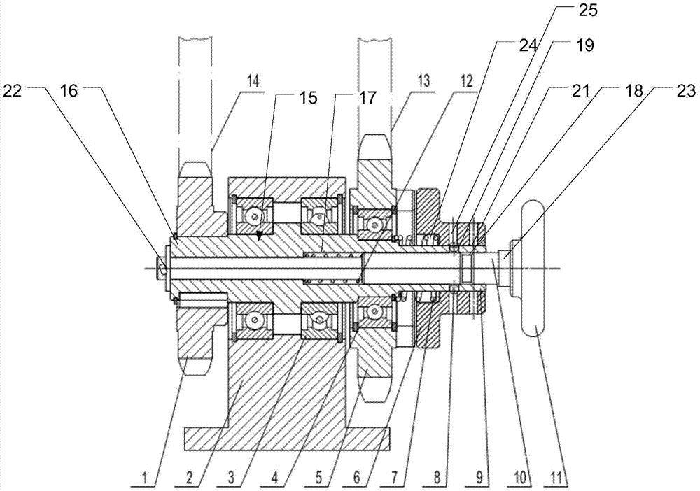
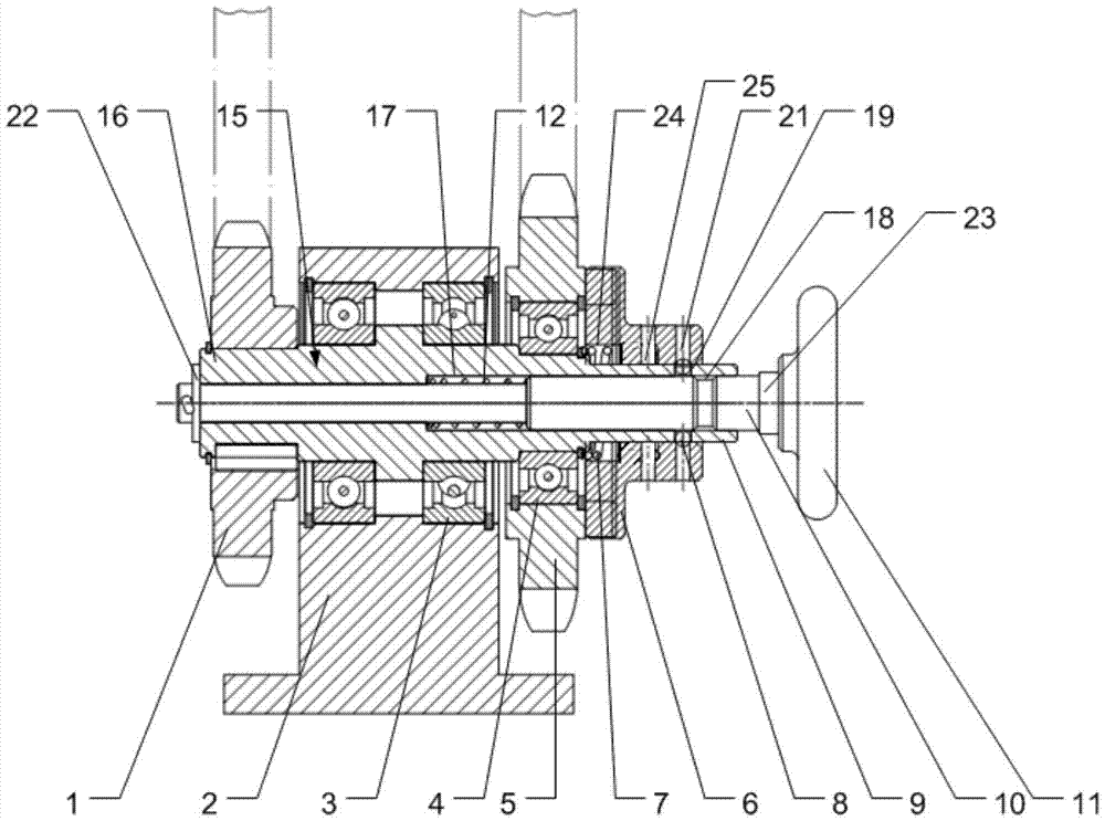
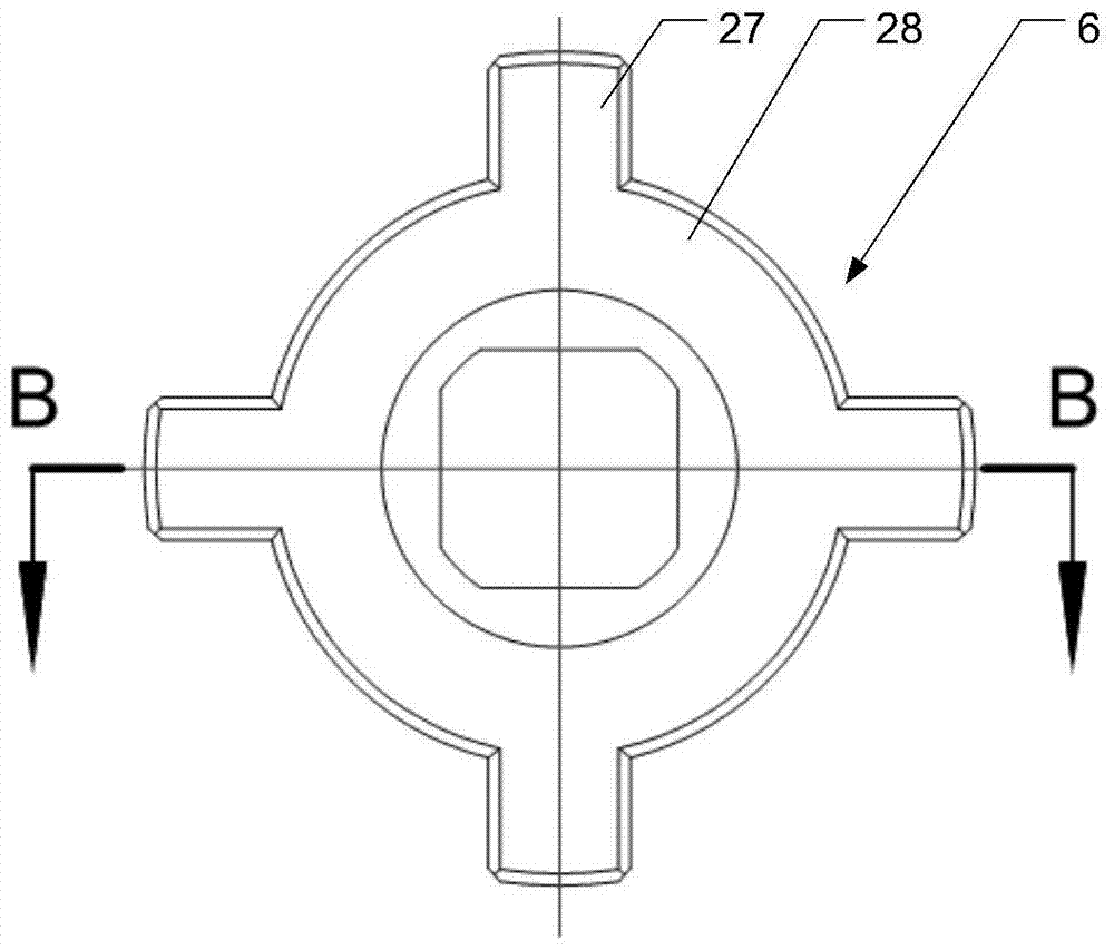
[0031] Such as figure 1 and figure 2 As shown, the present invention provides a clutch device, comprising: a clutch shaft 15, which has a shaft hole 17, wherein the driven sprocket 1 is fixed to the rear end 16 of the clutch shaft 15, and the driving sprocket 5 Rotatably sleeved on the middle section of the clutch shaft 15; clutch chuck 6, which is slidably sleeved on the clutch shaft 15; control mandrel 10, which is slidably inserted into the shaft hole 17 , and the operating end 11 of the mandrel is located outside the front end 9 of the clutch shaft, the side wall of the mandrel 10 is provided with a groove 18; and a locking mechanism, which includes a ball 8, a first Locking hole 19, second locking hole 25 and third locking hole 21, wherein, the first locking hole 19 i...


PUM


Abstract

The invention discloses a clutch device, comprising: a clutch shaft, which has a shaft hole, a driven sprocket is fixed on the rear end of the clutch shaft, and a driving sprocket is rotatably sleeved on the middle section of the clutch shaft; a clutch chuck, which It is slidably sleeved on the clutch shaft; the control mandrel is slidably inserted into the shaft hole, and the side wall of the control mandrel is provided with a groove; and the locking mechanism includes a ball, a first locking hole, In the second locking hole and the third locking hole, the ball is freely arranged in the first locking hole and passes through the first locking hole; when the clutch chuck slides to the separation position or the joint position, a part of the ball enters into the second locking hole. The locking hole or the third locking hole is used to lock the clutch chuck so that the clutch chuck and the drive sprocket are kept separated from each other or engaged with each other; the control core moves to the rear end of the clutch shaft to make Part of the ball enters the groove, thereby releasing the lock. The invention realizes the clutch of the driving sprocket and the driven sprocket.

Description

technical field [0001] The invention relates to a clutch device. Background technique [0002] In the current car washer, the horizontal brush is used to scrub the top of the vehicle, and the horizontal brush is arranged on the top of the frame in a manner that can rotate relative to the frame. In the prior art, the horizontal brush is directly connected to the motor through a transmission mechanism without using a clutch device. This results in that the connection and separation between the horizontal brush and the motor, or between the horizontal brush and the transmission mechanism cannot be realized conveniently, and the working conditions of the car washing machine cannot be changed and controlled as required. Contents of the invention [0003] In view of the above technical problems, the present invention provides an easy-to-use clutch device that can realize the clutch of the driving sprocket and the driven sprocket. [0004] The technical scheme provided by the i...

Claims


Application Information

Patent Timeline
Patent Type & Authority Patents(China)
IPC IPC(8): F16D15/00
Inventor 张宝存戴文明
Owner WASHING BEIJING AUTOMATIC EQUIP
Learn More