Power Transmission Mechanism for Electric Vehicles

A technology of power transmission mechanism and vehicle, which is applied to electric components, transmission devices, electromechanical devices, etc., can solve the problems of impossibility, low deceleration effect, difficulty in smooth operation, etc., and achieve the effect of improving braking effect

Inactive Publication Date: 2019-04-12
林美华
View PDF12 Cites 1 Cited by
  • Summary
  • Abstract
  • Description
  • Claims
  • Application Information

AI Technical Summary

Problems solved by technology

[0005] However, after analyzing the structure of the new patent, the applicant in this case believes that it has many unenforceable deficiencies
Among them, the most important point is that the two output shafts are independent and not connected, which makes it difficult for the first planetary gear module and the second planetary gear module to move smoothly when rotating, and it is easy to be biased and cause the output shaft to be stuck or broken , in this way, it is easy to reduce the deceleration effect or malfunction, so it is necessary to improve

Method used


Image

  • Power Transmission Mechanism for Electric Vehicles
  • Power Transmission Mechanism for Electric Vehicles
  • Power Transmission Mechanism for Electric Vehicles

Examples


Embodiment Construction

[0033] The present invention will be described in further detail below in conjunction with the accompanying drawings.

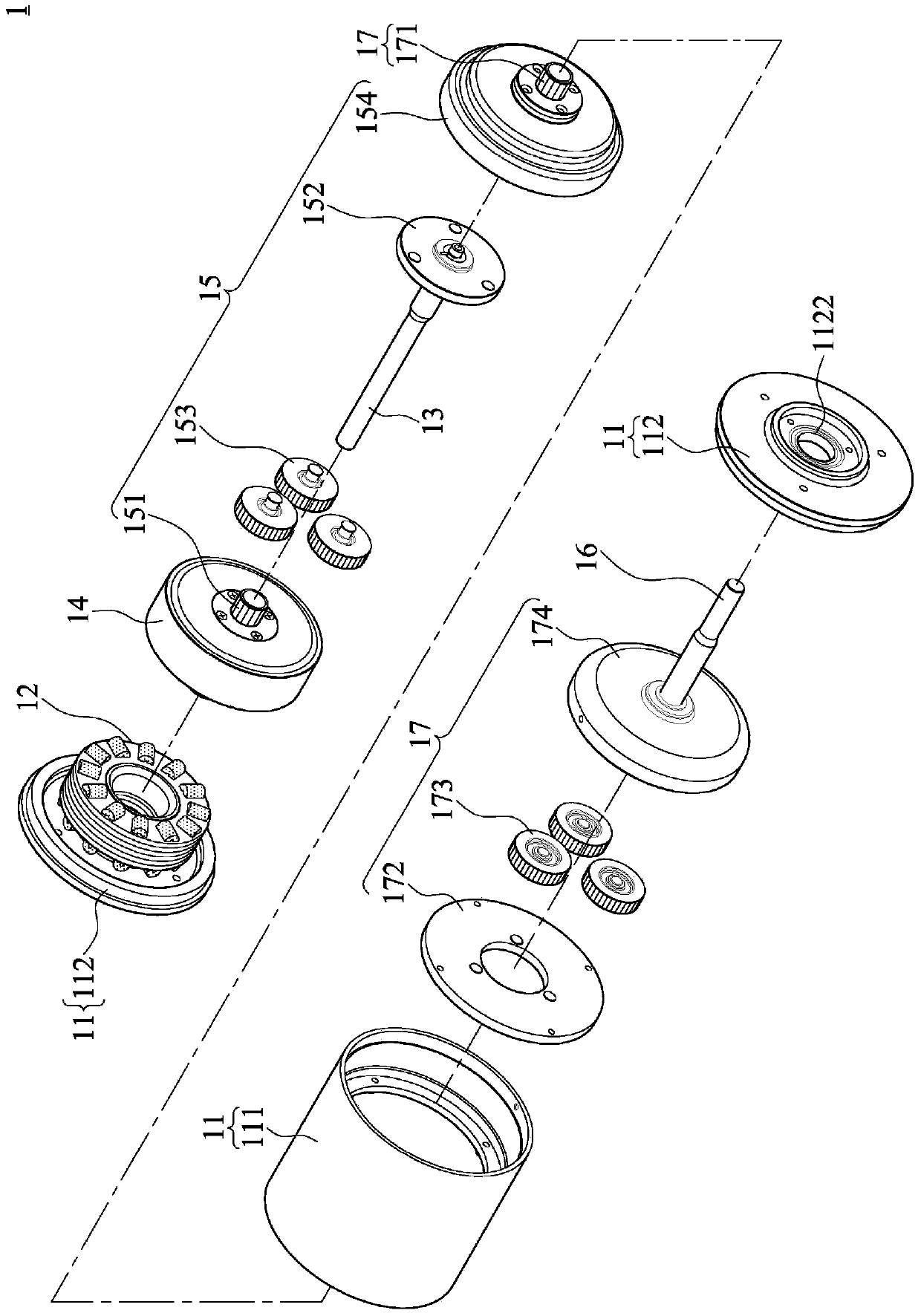
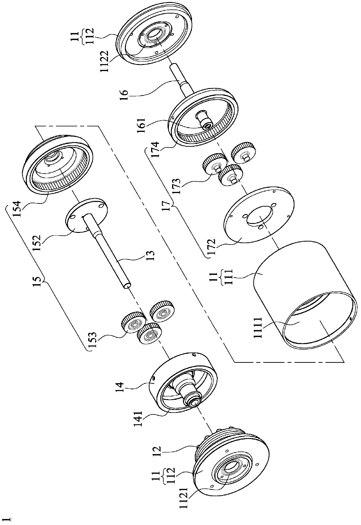
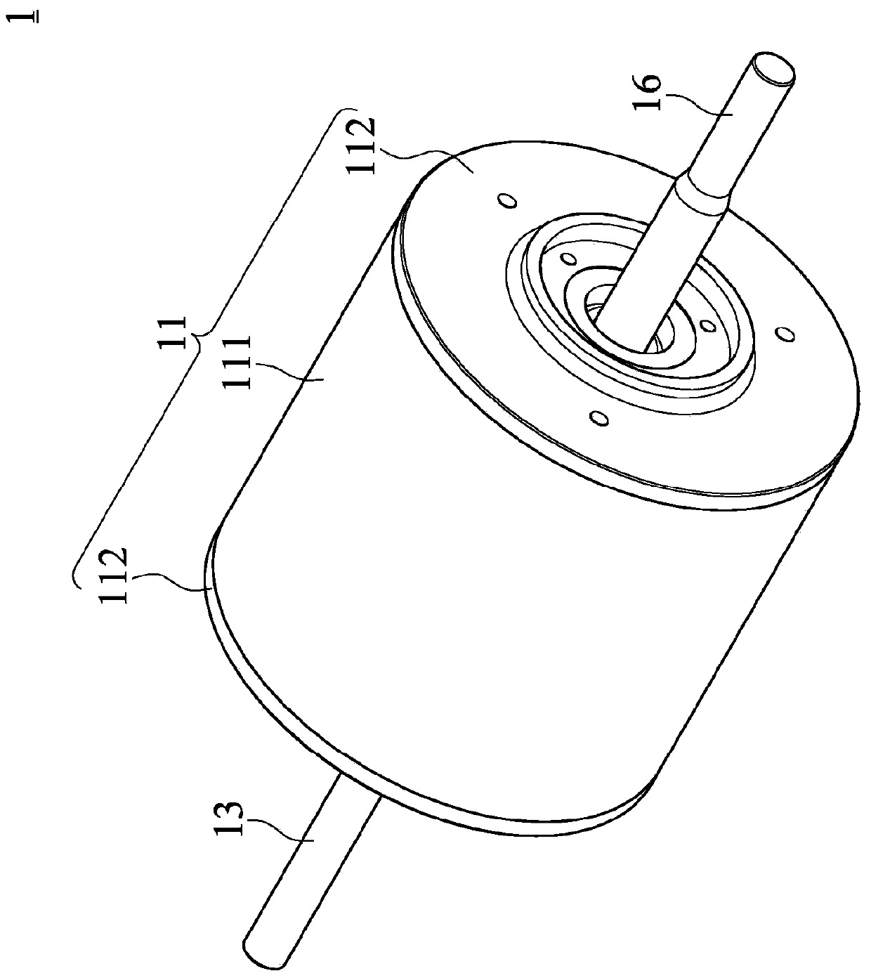
[0034] Such as Figure 1~4 and Figure 9 As shown, the power transmission mechanism 1 of the electric vehicle of the present invention is fixed on the electric vehicle 2 for driving the wheels 21 on both sides of the electric vehicle 2 respectively. The power transmission mechanism 1 of the electric vehicle includes a housing 11 , a motor stator 12 , a first output shaft 13 , a motor rotor 14 , a first planetary reduction module 15 , a second output shaft 16 and a second planetary reduction module 17 .

[0035] Wherein the housing 11 includes a tube body 111 and two caps 112. The inside of the tube body 111 forms an accommodating space 1111. The two caps 112 are respectively used to close the openings at both ends of the tube body 111, and one of the caps The opening in the center of 112 corresponds to the first output shaft 13 and is provided with a first ...


PUM


Abstract

The invention belongs to the field of transmission mechanisms for electric carriers, in particular to a power transfer mechanism of an electric carrier, which uses single rotating power source for respectively driving two planetary reduction modules and two output shafts to perform the differential output. The power transfer mechanism of the electric carrier comprises a shell, a motor stator, a first output shaft, a motor rotor, a first planetary reduction module, a second output shaft and a second planetary reduction module, wherein the motor stator, the motor rotor, the first planetary reduction module and the second planetary reduction module are respectively accommodated in the shell; the first planetary reduction module is connected with the first output shaft; the second planetary reduction module is connected with the second output shaft; and the first output shaft and the second output shaft are connected by a movable positioning mechanism, so that the first output shaft and the second output shaft respectively perform the differential output by the first planetary reduction module and the second planetary reduction module to achieve a differential effect of double output power sources by single power source.

Description

technical field [0001] The invention belongs to the field of transmission mechanisms used by electric vehicles, and specifically relates to a power transmission mechanism for electric vehicles that utilizes a single rotating power source to respectively drive two planetary reduction modules and two output shafts for differential output. Background technique [0002] Generally, electric vehicles such as electric scooters, factory trucks, golf carts, electric ATVs, etc., because the load is low and does not require fast speeds, and does not need to use fossil fuel engine structures, most of them use electric vehicles. The motor is used as a rotating power source, which is driven by the electric power of the battery, so it will not cause air pollution. [0003] However, most of the electric motors used in electric vehicles adopt high-speed design, and with the appropriate power transmission mechanism, the high-speed power of the electric motor can be converted into high-torque ...

Claims


Application Information

Patent Timeline
Patent Type & Authority Patents(China)
IPC IPC(8): F16H1/32H02K7/116
Inventor 林美华
Owner 林美华
Why Eureka
Try Eureka