Micro-drive system and clamping system comprising same

A micro-driven and driven technology, applied in the field of mechanical clamping, can solve the problems of small piston rod size, instability and damage of the pressure rod, and large device volume, and achieve the effects of reducing energy conversion links, improving utilization rate, and small size

Inactive Publication Date: 2013-09-11
SUZHOU UNIV
View PDF7 Cites 3 Cited by
  • Summary
  • Abstract
  • Description
  • Claims
  • Application Information

AI Technical Summary

Problems solved by technology

[0006] However, there are certain defects in the traditional area effect travel amplification device
When determining the magnification, if the size of the driving piston is limited, the size of the output piston will also be fixed, and in order to place the return spring in the rod cavity, the size of the output piston rod must be sacrificed, which may cause the size of the piston rod to be too large. Small, insufficient rigidity, problems such as instability and damage of the pressure rod; on the contrary, if the rigidity of the output piston rod is guaranteed, the size of the output piston must be enlarged, and the size of the driving piston will also increase accordingly, so that the entire device is too large and the cost High, inconvenient to operate

Method used


Image

  • Micro-drive system and clamping system comprising same
  • Micro-drive system and clamping system comprising same
  • Micro-drive system and clamping system comprising same

Examples


Embodiment 1

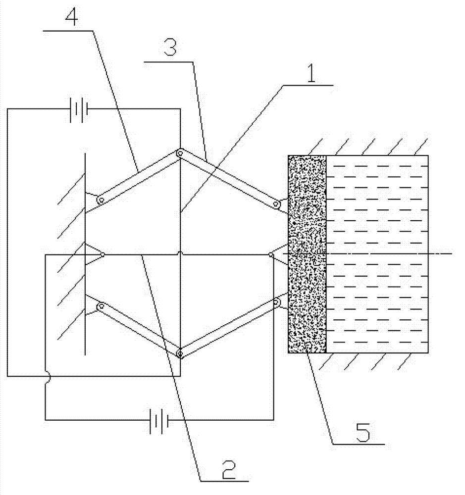
[0036] See figure 1 , figure 1 It is a structural schematic diagram of a micro-drive system disclosed in the present invention. As shown in the figure, a micro-drive system is used to provide a small amount of displacement to drive the driven part to run, wherein the driven part is the driving piston in the stroke amplification device.

[0037] The system includes a driving device and a control device, and the driving device includes a pushing mechanism and a reset mechanism connected with the driving piston 5 .

[0038] The pushing mechanism includes a first shape memory alloy rod 1 that drives the driving piston to move forward, and a transmission rod assembly symmetrically arranged at both ends of the first shape memory alloy rod 1. One end of the transmission rod assembly is fixed, and the other end is hingedly connected to the driving piston. The transmission rod assembly At least two groups. The number of transmission rod assemblies may be symmetrically arranged in mu...
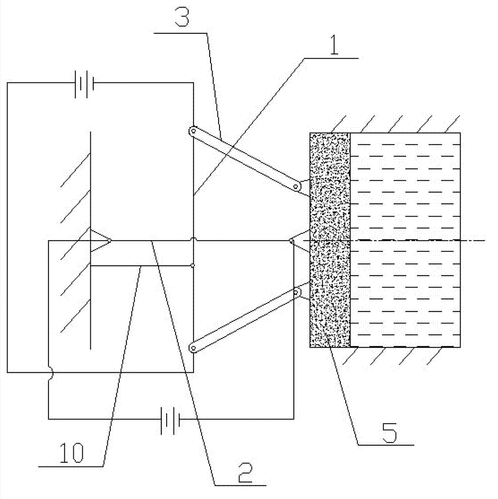
Embodiment 2

[0058] Such as figure 2 As shown, the rest are the same as in Embodiment 1, the difference is that the transmission rod assembly includes a first transmission rod 3, one end of the first transmission rod is hinged to the first shape memory alloy rod, and the other end of the first transmission rod 3 is connected to the The workpiece is hinged and fixed, a positioning rod 10 is connected to the first shape memory alloy rod 1, and one end of the positioning rod 10 is fixed. By setting the positioning rod to limit the position of the first shape-memory alloy rod 1, only by changing the angle between the first shape-memory alloy rod and the first transmission rod during the expansion and contraction of the first shape-memory alloy rod, the workpiece can be adjusted move forward.

[0059] The invention discloses a micro-drive system and the advantages of the clamping system including the system are:

[0060] Based on the shape memory effect, two shape memory alloy rods perpendic...


PUM


Abstract

The invention discloses a micro-drive system and a clamping system comprising the micro-drive system. The micro-drive system is based on a shape memory effect and is driven by two shape memory alloy rods which are mutually perpendicular, a first shape memory alloy rod is electrified and contracts to push a drive piston to move forwards through a transmission rod assembly, a second shape memory alloy rod is electrified and contracts to drive the drive piston to reset, and at the same time, the two shape memory alloy rods can respectively serve as a drawing power source of each other to produce plastic deformation. The clamping system comprises the micro-drive system and an internal reflux area differential stroke amplifying device, due to the fact that a reflux hole is formed in an output piston, the differential effect is achieved, the effective acting area of the output piston is made to be only the cross sectional area of a piston rod, and therefore the amplification coefficient is improved on the basis of reduction of the size of the stroke amplifying device. Compared with a traditional drive clamping device, the clamping system is small in size, simple in structure, good in controllability, fewer in energy conversion steps, high in utilization rate of energy, free of pollution, and capable of protecting environment.

Description

technical field [0001] The invention belongs to the technical field of mechanical clamping, and in particular relates to a micro-drive system and a clamping system including the system. Background technique [0002] At present, hydraulic or pneumatic methods are widely used in the manufacturing industry for clamping. However, the current clamping methods have some shortcomings, such as: 1. Hydraulic clamps need to provide pressure oil pumps, pneumatic clamps need to provide compressed air air compressors, and drive source mechanisms Complex, high cost, and large volume; 2. There are many energy conversion links to provide the required clamping force, the energy loss is large, and the energy utilization rate is low; 3. There is a high-speed rotating mechanical transmission device, and the noise pollution is relatively serious. In addition, the hydraulic device also has the problem of oil leakage and pollution of the environment, which is likely to cause environmental pollutio...

Claims


Application Information

Patent Timeline
Patent Type & Authority Applications(China)
IPC IPC(8): F03G7/06B25B11/00
Inventor 李知瑶钟康民王传洋
Owner SUZHOU UNIV
Why Eureka
Try Eureka