Magnetic particle flow power generation system having no rotary movement

A power generation system and rotary motion technology, applied in electrical components, electromechanical devices, etc., can solve problems such as movement form restrictions, and achieve the effect of reducing manufacturing difficulty, simple structure, flexible structure and layout

Active Publication Date: 2015-04-01
TSINGHUA UNIV
View PDF3 Cites 2 Cited by
  • Summary
  • Abstract
  • Description
  • Claims
  • Application Information

AI Technical Summary

Problems solved by technology

[0004] In addition, the magnetic circuit of the existing motor uses an iron core to form a magnetic circuit, which has a fixed shape, and the fixed shape has a restrictive effect on its motion form

Method used


Image

  • Magnetic particle flow power generation system having no rotary movement
  • Magnetic particle flow power generation system having no rotary movement
  • Magnetic particle flow power generation system having no rotary movement

Examples


Embodiment Construction

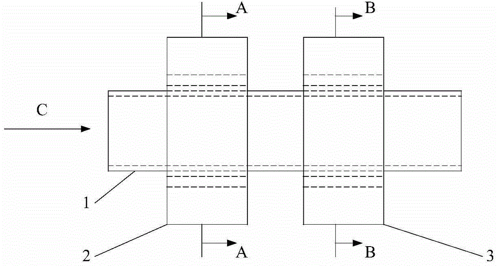
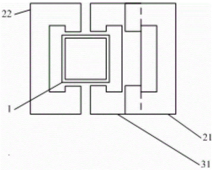
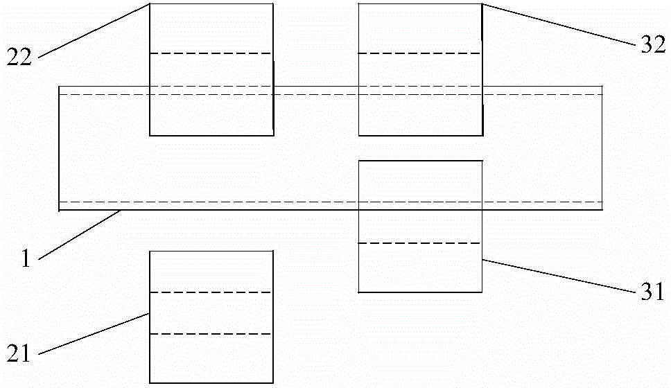
[0027] The invention relates to a magnetic particle flow power generation system without rotating motion. The system adopts a direct coupling method of a prime mover and a magnetic particle flow power generation system to generate electricity, eliminating the need for rotating parts such as turbines. The prime mover can be a gas engine, a steam engine or a diesel engine. Take a gas engine as an example. The structure of the gas engine is similar to the previous gas engine. The air is compressed by the compressor and enters the combustion chamber of the gas engine to mix and burn with the fuel. The gas expands rapidly when heated. . At this time, the magnetic particles of the present invention are sprayed into the combustion chamber, and the magnetic particles are mixed with the gas, driven by the gas to move at a high speed, and carry kinetic energy. A large number of magnetic particles form a flow of magnetic particles and move at a high speed in the conduit. The attraction of...


PUM


Abstract

The invention relates to a magnetic particle flow power generation system having no rotary movement. The power generation system is characterized in that the magnetic particle flow power generation system is directly coupled with a prime motor; and the magnetic particle flow power generation system comprises a diversion pipe, a modulation magnetic circuit, a power generation magnetic circuit and magnetic particles. One end of the diversion pipe is provided with the modulation magnetic circuit, and the other end of the diversion pipe is provided with the power generation magnetic circuit; the magnetic particles are arranged in the diversion pipe; the magnetic particles form magnetic particle flow in the inner side of the diversion pipe under the action of magnetic force and expansion gases obtained after combustion in the prime motor; the power generation magnetic circuit realizes changes of magnetic circuit magnetic reluctance by utilizing the changes of the magnetic particle flow magnetic reluctance, and thus power generation and electrical operation are realized; the modulation magnetic circuit is in horizontal movement along the direction vertical to cross section of the diversion pipe; and the position of the power generation magnetic circuit is fixed with respect to the diversion pipe. The magnetic particle flow power generation system is simple in structure, can effectively improve energy utilization efficiency, has no rotation members, and can be widely used in a power generation system.

Description

Technical field [0001] The invention relates to a power generation system, in particular to a magnetic particle current power generation system without rotating motion. Background technique [0002] A gas turbine uses a continuous flow of gas as a working medium to convert heat energy into mechanical energy, and is a rotary power machine. A gas turbine consists of three major components: a compressor, a combustion chamber and a gas turbine. The compressor sucks in air from the outside. After the air is compressed and pressurized by the compressor, the temperature and pressure increase. The compressed air is sent into the combustion chamber and mixed with the injected fuel to generate high temperature and high pressure gas. The gas enters the turbine to expand and perform work, which drives the turbine. At the same time, the turbine drives the compressor and the rotor to rotate at a high speed. The rotor drives the generator to rotate to realize the conversion of the chemical ene...

Claims


Application Information

Patent Timeline
Patent Type & Authority Applications(China)
IPC IPC(8): H02K44/00H02K44/16
Inventor 王善铭柴建云孙旭东王祥珩苏鹏声
Owner TSINGHUA UNIV
Why Eureka
Try Eureka