Window locking device
A locking device and window technology, applied in the field of door and window parts, can solve problems such as hidden dangers, sliding displacement of window frames, theft, etc., and achieve the effects of high safety factor, increased safety, and convenient installation.
- Summary
- Abstract
- Description
- Claims
- Application Information
AI Technical Summary
Problems solved by technology
Method used
Image

Examples
Embodiment 1
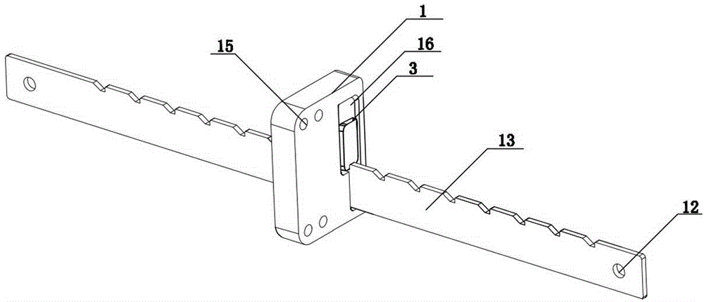
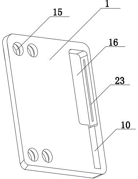
[0025] Example 1, such as figure 1 with 2 shown. The present invention includes an inner window frame and an outer window frame, and the window locking device structure includes a rack 13 and a base 1 . The base 1 is provided with threaded holes 15, and the base 1 is connected with the inner window frame by bolts. The rack 13 is provided with a fixing hole 12, and the rack 13 is connected with the outer window frame by bolts. The base 1 is provided with a sliding hole 10 , and the size of the sliding hole 10 matches the rack 13 , so that the rack 13 can slide relative to the base 1 along the sliding hole 10 . The base 1 is also provided with a limiting device, such as figure 1 As shown, the limiting device is composed of a limiting member 3 and a chute 16, and the limiting member 3 is a limiting plate. Slide rails 23 are provided on both sides of the wall of the chute 16 , and the stopper 3 slides up and down along the slide rails 23 . The rack 13 is provided with a lock...
Embodiment 2
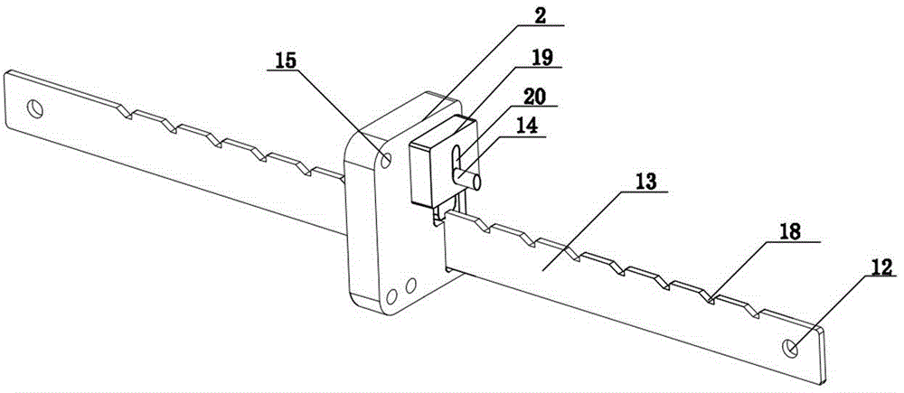
[0027] Example 2, such as Figures 3 to 5 As shown, this embodiment is based on Embodiment 1. The limiting device includes a limiting member 3, a control member 14 and a chute 16. A positioning pin 17 is riveted on the limiting member 3, and a positioning pin 17 is sleeved on the limiting member 3. Return spring 9, and return spring 9 is fixedly connected with chute 16 walls. Such as Figure 5 As shown, the control member 14 is a control rod, and the control rod is riveted with the surface of the limiting member 3 . In order to make the sealing of the limit device better, such as image 3 As shown, a seal 19 is provided on the outside of the chute 16 , and the seal 19 is fixedly connected to the base 1 . The sealing member 19 is provided with a through hole 20, and the control member 14 can pass through the through hole 20 for the user to operate the limiting device.
[0028] The principle of use is the same as that of Embodiment 1, and the locking member 3 is moved up and...
Embodiment 3
[0029] Example 3, such as Figures 6 to 8 As shown, this embodiment is based on Embodiment 2, and the structure of the sealing member 19 is replaced by the lock cylinder base 2. The lock cylinder base 2 is provided with a lock cylinder connector 8, and the inside of the lock cylinder connector 8 is hollow. The lock cylinder base 2 is fixedly connected with the base 1 by screws, such as Figure 8 As shown, the lock cylinder base 2 is provided with a No. 2 sliding hole 11, and the No. 2 sliding hole 11 is set in cooperation with the sliding hole 10 on the base 1, so that the rack 13 passes through the sliding hole 10 and the second sliding hole at the same time. No. 11. The control piece 14 is connected with a lock core 6 , and the tail end of the lock core 6 is provided with a puller 4 , and the puller 4 rotates with the rotation of the lock core 6 . The pulling piece 4 is provided with an adjusting rod 21 , and the adjusting rod 21 abuts against the bottom of the control mem...
PUM
 Abstract
Description
Claims
Application Information
 - R&D
- Intellectual Property
- Life Sciences
- Materials
- Tech Scout
- Unparalleled Data Quality
- Higher Quality Content
- 60% Fewer Hallucinations
Browse by: Latest US Patents, China's latest patents, Technical Efficacy Thesaurus, Application Domain, Technology Topic, Popular Technical Reports.
© 2025 PatSnap. All rights reserved.Legal|Privacy policy|Modern Slavery Act Transparency Statement|Sitemap|About US| Contact US: help@patsnap.com