Method for recirculation of exhaust gas and gas turbine for conducting said method

A gas turbine and recirculation technology, which is applied in gas turbine installations, flue gas combustion, combustion methods, etc.

Inactive Publication Date: 2016-01-27
ANSALDO ENERGIA SWITZERLAND AG
View PDF21 Cites 4 Cited by
  • Summary
  • Abstract
  • Description
  • Claims
  • Application Information

AI Technical Summary

Problems solved by technology

[0007] Although known flue gas recirculation solutions lead to better emission properties of gas turbines, they are associated with considerable additional equipment complexity and require considerable investment

Method used


Image

  • Method for recirculation of exhaust gas and gas turbine for conducting said method
  • Method for recirculation of exhaust gas and gas turbine for conducting said method
  • Method for recirculation of exhaust gas and gas turbine for conducting said method

Examples


Embodiment Construction

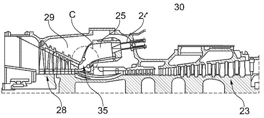
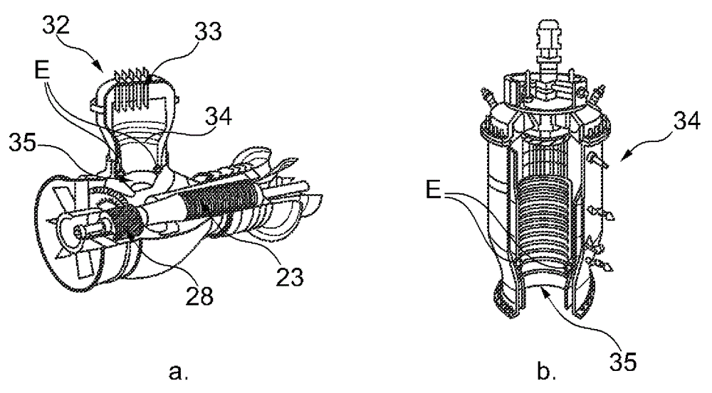
[0068] In the present invention a system is proposed wherein a novel passive flue gas recirculation is proposed. Recirculation is done inside the engine directly at the burner. Such configurations are well suited for sequential annular combustion systems (as in GT24 / GT26, see Figure 5 ), annular combustion (GT13E2, see Figure 6 ), can burner construction (see Figure 7 ) or silo burners (GT11N2, see Figure 8 ).

[0069] Systems used to recirculate exhaust gas should be designed to be capable of recirculating 10%-50%. This means that the flue gas (or exhaust) content of the air / flue gas mixture ranges from 10% to 50%.

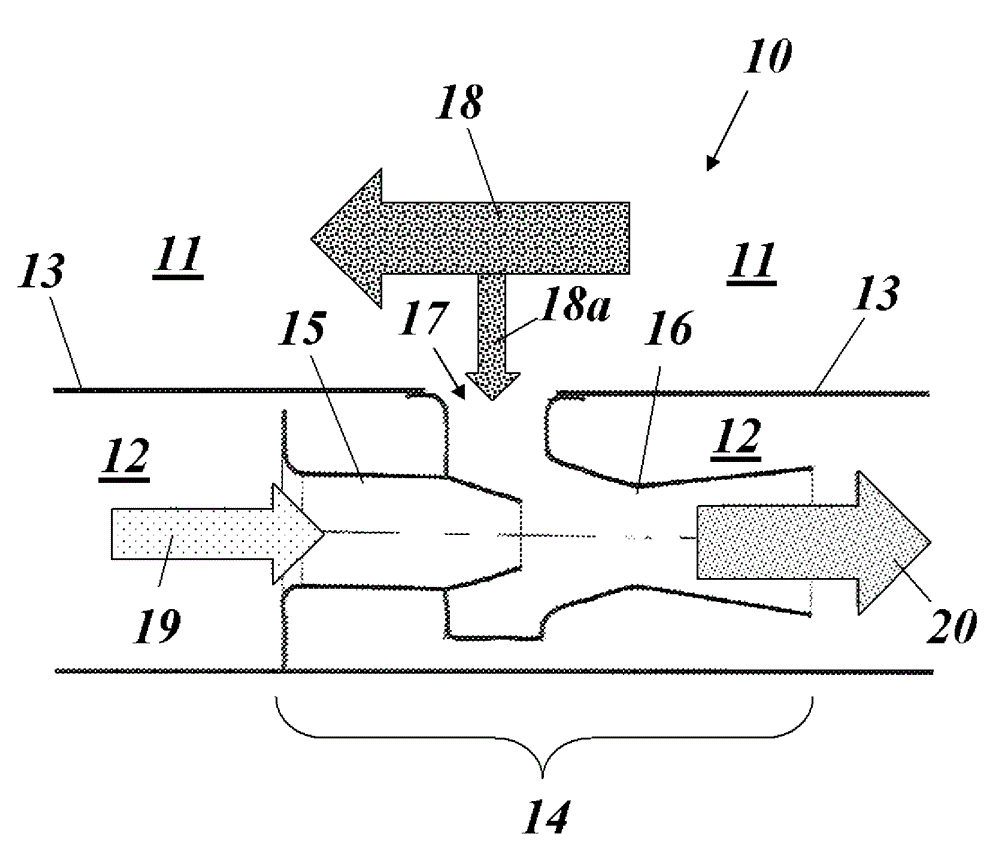
[0070] Such as figure 2 As shown in FIG. 2 , a combustor liner wall 13 encloses a combustion chamber 11 of a combustor 10 of a gas turbine. Exhaust gas (flue gas) 18 flows from right to left in this example to exit the combustor and enter a subsequent turbine section with rotating blades (not shown). Cooling air channels 12 are arranged on the outsid...


PUM


Abstract

A method for recirculation of exhaust gas (18) from a combustion chamber (11) of a combustor (10) of a gas turbine back to the supply side of said combustor (10) is characterized in that a partial flow (18a) of the exhaust gas (18) in said combustion chamber (11) is directly extracted from said combustion chamber (11) and internally fed back to an entrance of the combustor (10) through an internal channel (12) of said combustor (10).

Description

technical field [0001] The present invention relates to the technology of gas turbines. It relates to a method according to the preamble of claim 1 for recirculating exhaust gas from a combustion chamber of a combustor of a gas turbine. [0002] It further relates to a gas turbine for carrying out the method. Background technique [0003] A reheat system (sequential combustion) or a staged system incorporated eg in the applicant's GT24 type gas turbine proved to be excellent in achieving very low emissions at high combustion temperatures. [0004] Such combustion systems also meet a number of stringent requirements such as: low pressure drop, low cooling air consumption, long life and fuel flexibility. One of the key elements upon which such systems depend is the level of mixing achieved between the hot gas and the fuel or fuel / air mixture prior to the flame. [0005] The concepts developed so far provide very good mixing levels and combustion performance. However, they ...

Claims


Application Information

Patent Timeline
Patent Type & Authority Applications(China)
IPC IPC(8): F23R3/00
CPCF23R3/06F23C9/00F23R3/46F23C9/08F23C2202/30F23C2900/09002F02C3/34
Inventor H.克内普费T.鲁克M.佩雷蒂
Owner ANSALDO ENERGIA SWITZERLAND AG
Why Eureka
Try Eureka