
UAV dual-camera multi-angle shooting support device and control method

A technology of a supporting device and a dual camera, applied in the field of unmanned aerial vehicles, can solve the problems of small field of view coverage, low efficiency, and inability to automatically control, and achieve the effect of large field of view coverage, high work efficiency, and multiple shooting angles.

Inactive Publication Date: 2018-09-18
INST OF REMOTE SENSING & DIGITAL EARTH CHINESE ACADEMY OF SCI
View PDF6 Cites 0 Cited by
  • Summary
  • Abstract
  • Description
  • Claims
  • Application Information

AI Technical Summary

Problems solved by technology

However, there are deficiencies in this fixed frame: first, the shooting angle cannot be adjusted; second, even if the shooting angle can be manually adjusted, multi-angle shooting cannot be obtained; third, manual adjustment of the shooting angle cannot be automatically controlled, and the field of view coverage Small size, unable to obtain mobile phones according to needs; time-consuming and labor-intensive, low efficiency; Fourth, manually adjusting the shooting angle, time-consuming and labor-intensive, low efficiency

Method used


Image

  • UAV dual-camera multi-angle shooting support device and control method
  • UAV dual-camera multi-angle shooting support device and control method
  • UAV dual-camera multi-angle shooting support device and control method

Examples


Embodiment Construction

[0026] The following examples are used to illustrate the present invention, but are not intended to limit the scope of the present invention.

[0027] see Figure 1-6 :

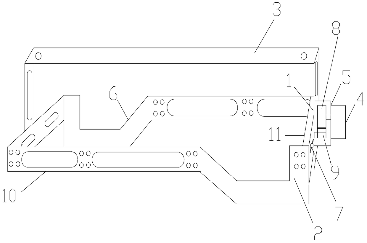
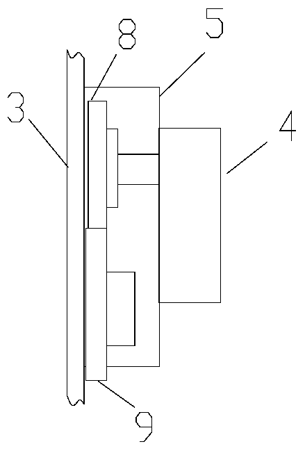
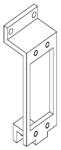
[0028] The present invention is an unmanned aerial vehicle dual-camera multi-angle shooting support device of the present invention, including a frame, a control device, a motor, a steering gear, a support shaft, a turret, a limiter, and a latch, and the two ends of the turret are respectively Hinged with the two short sides of the frame, the steering gear is fixed at one end of the turret, and the lower part of the steering gear is fixedly connected to the frame through the support shaft, the pin passes through the frame and the support shaft, so that the support shaft is positioned on the frame, and the dual cameras are fixed In the frame, the top of the turntable is fixed on the bottom of the UAV, the control device is connected to the motor, and the motor is connected to the steering gear. The control d...


PUM


Abstract

The invention relates to a double-camera and multi-angle shooting supporting device for an unmanned aerial vehicle. The double-camera and multi-angle shooting supporting device for the unmanned aerial vehicle comprises a frame, a control device, a motor, a steering engine, a supporting shaft, a rotating stand, a limiting piece and a bolt, wherein two ends of the rotating stand are respectively hinged with two short edge pieces of the frame; the steering engine is fixed at one end of the rotating stand; the lower part of the steering engine is fixedly connected with the frame through the supporting shaft; the bolt penetrates through the frame and the supporting shaft so that the supporting shaft is located on the frame; double cameras are fixed within the frame; the top of the rotating stand is fixed at the bottom of the unmanned aerial vehicle; the control device is connected with the motor; the motor is connected with the steering engine; the limiting piece is fixed on a short edge piece of the frame and positioned on the two sides of the steering engine; the control device controls the motor; the motor drives the steering engine so that the steering engine drives the rotating stand to rotate; therefore, the double cameras can realize multi-angle shooting on the frame; and during the rotating of the rotating stand, the rotating angle of the rotating stand can be determined through the limiting piece. The double-camera and multi-angle shooting supporting device for the unmanned aerial vehicle, provided by the invention, is advantaged in that the efficiency of the double-camera and multi-angle shooting supporting device is high, the shooting angles of the cameras can be automatically controlled and adjusted, and various shooting angles are realized.

Description

technical field [0001] The invention belongs to an unmanned aerial vehicle, in particular to an unmanned aerial vehicle dual-camera multi-angle shooting support device and a control method. Background technique [0002] In the past, the drone camera shooting bracket can fix the camera on the drone. After the drone takes off, the camera can stably obtain ground data. However, there are deficiencies in this fixed mount: first, the shooting angle cannot be adjusted; second, even if the shooting angle can be adjusted manually, multi-angle shooting cannot be obtained; third, the manual adjustment of the shooting angle cannot be automatically controlled, and the field of view coverage Small size, unable to obtain mobile phones according to needs; time-consuming and labor-intensive, low efficiency; fourthly, manually adjusting the shooting angle, time-consuming and labor-intensive, low efficiency. Contents of the invention [0003] The purpose of the present invention is to prov...

Claims


Application Information

Patent Timeline
Patent Type & Authority Patents(China)
IPC IPC(8): B64D47/08
Inventor 谭骏翔左正立
Owner INST OF REMOTE SENSING & DIGITAL EARTH CHINESE ACADEMY OF SCI
Learn More