Cooling structure for electrical storage device

一种蓄电装置、冷却结构的技术,应用在结构零件、电路、电气元件等方向,能够解决导热片壁厚厚、不经济等问题,达到抑制温度的不均、抑制流出、实现轻量化的效果

Active Publication Date: 2016-02-03
HONDA MOTOR CO LTD
View PDF4 Cites 9 Cited by
  • Summary
  • Abstract
  • Description
  • Claims
  • Application Information

AI Technical Summary

Problems solved by technology

However, the wall thickness of the heat transfer sheet becomes considerably thicker, and there is a problem that the cooling structure as a whole becomes large and heavy, which is uneconomical.

Method used


Image

  • Cooling structure for electrical storage device
  • Cooling structure for electrical storage device
  • Cooling structure for electrical storage device

Examples


Embodiment Construction

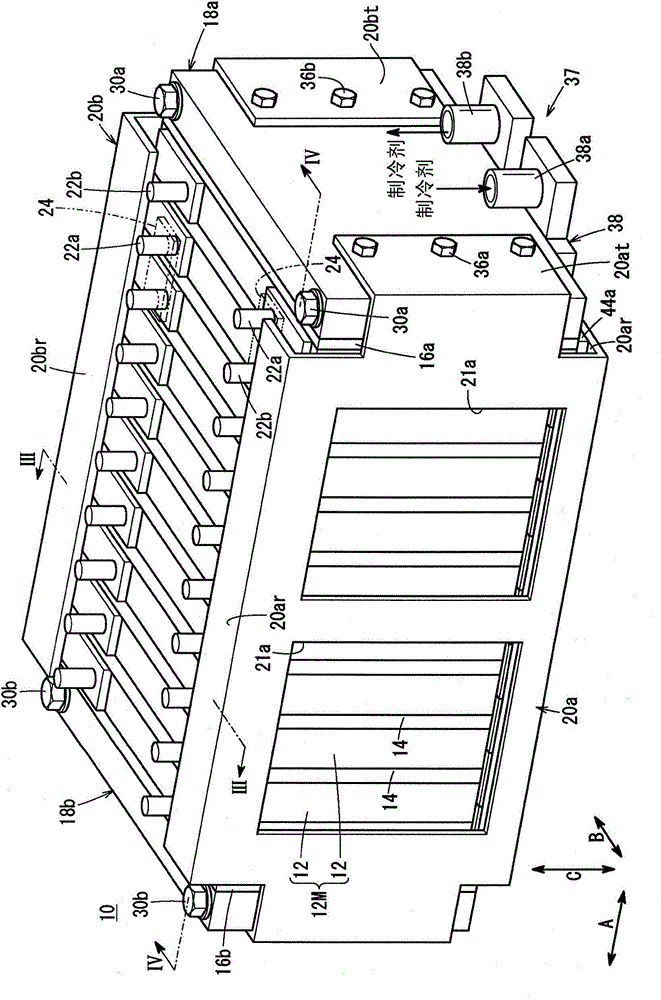
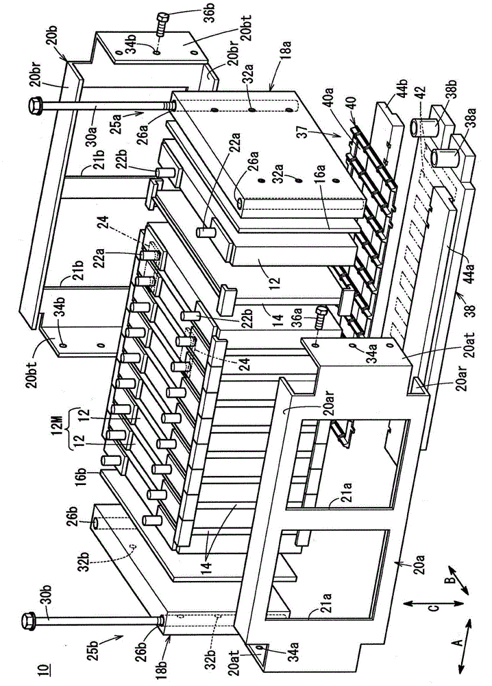
[0046] Such as figure 1 and figure 2 As shown, the power storage module 10 according to the embodiment of the present invention is mounted on, for example, an electric vehicle such as a hybrid vehicle or an EV (not shown).

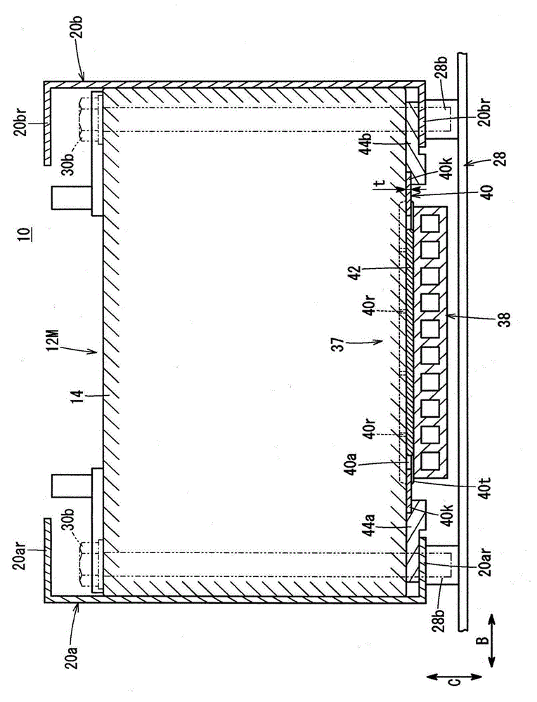
[0047] The power storage module 10 includes a battery pack (battery module) 12M in which a plurality of batteries (battery cells) 12 are stacked in the horizontal direction (arrow A direction). The storage battery 12 has a rectangular shape, and is stacked alternately with insulating separators (holders) 14 in the arrow A direction in a state of being arranged in an upright posture.

[0048] Such as figure 2 As shown, at both ends of the stacking direction of the battery pack 12M, insulating plates (or separators 14) 16a, 16b having heat insulation and insulation functions are sandwiched to arrange rectangular end plates 18a, 18b. The end plates 18a, 18b are disposed at both ends in the direction of arrow B, and are connected by, for example, a pair o...


PUM


Abstract

The present invention provides a cooling structure for an electrical storage device. The cooling structure for an electrical storage device can realize light weight and compactness, and can preferably cooling each storage battery in an economic structure. The cooling structure (37) for an electric power storage module (10) is provided with a radiator (38) for cooling a storage battery set (12M) and a separation component (40) which is arranged between the storage battery set (12M) and the radiator (38) and is provided with a plurality of division areas (40a) which are divided according to each storage battery. Heat conduction gels (42) are accommodated in each division area (40a), and integrally contact the storage battery (12) and the radiator (38).

Description

technical field [0001] The present invention relates to a cooling structure of a power storage device having a battery pack formed by stacking a plurality of batteries. Background technique [0002] Generally, an electricity storage module is known that includes a battery pack (battery module) in which a plurality of batteries (battery cells) are stacked. This power storage module is mounted on an electric vehicle such as a hybrid vehicle or an EV. [0003] In the electricity storage module, the performance and life of the storage battery depend on temperature, and the storage battery tends to deteriorate when the temperature becomes high. Therefore, in order to improve the durability of the battery, it is necessary to cool the battery well. Therefore, for example, a cooling structure for a battery pack disclosed in Patent Document 1 is known. [0004] In this cooling structure, a battery pack is formed by arranging a plurality of prismatic batteries with insulating separ...

Claims


Application Information

Patent Timeline
Patent Type & Authority Applications(China)
IPC IPC(8): H01M10/613H01M10/617H01M10/653H01M50/209H01M50/289
CPCH01M10/625H01M10/653H01M10/647H01M10/6556H01M10/6554H01M10/613H01M10/6551Y02E60/10H01M50/209H01M50/289
Inventor 林田淳因和久
Owner HONDA MOTOR CO LTD
Why Eureka
Try Eureka