Fixing apparatus and image forming apparatus

Active Publication Date: 2018-10-16
KONICA MINOLTA INC
View PDF6 Cites 0 Cited by
  • Summary
  • Abstract
  • Description
  • Claims
  • Application Information

AI Technical Summary

Benefits of technology

[0010]The present disclosure was made to solve the problems as described above, and an object in one aspect is to provide a fixing apparatus and an image forming apparatus

Problems solved by technology

With arrangement of an excitation coil inside a heating rotator, however, when the timing to replace the heating rotator comes, the excitation coil is also simultaneously replaced together with the heating rotator, which increases co

Method used


Image

  • Fixing apparatus and image forming apparatus
  • Fixing apparatus and image forming apparatus
  • Fixing apparatus and image forming apparatus

Examples


first embodiment

[0034](Internal Configuration of Image Forming Apparatus)

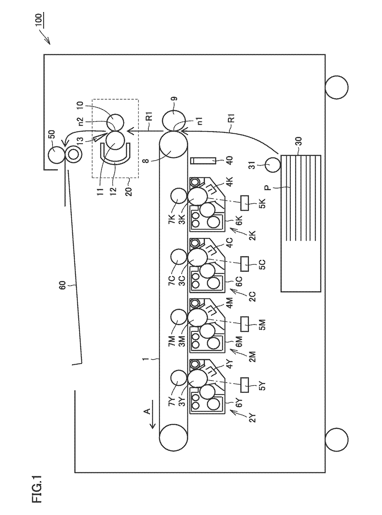
[0035]FIG. 1 is a cross-sectional view showing an internal configuration of an image forming apparatus 100 in a first embodiment. Image forming apparatus 100 includes an intermediate transfer belt 1 as a belt member substantially in a central portion of the inside. Four imaging units 2Y, 2M, 2C, and 2K corresponding to colors of yellow (Y), magenta (M), cyan (C), and black (K), respectively, are arranged as being aligned along intermediate transfer belt 1 under a lower horizontal portion of intermediate transfer belt 1 and have photoconductor drums 3Y. 3M, 3C, and 3K, respectively.

[0036]Chargers 4Y, 4M, 4C, and 4K, print head portions 5Y, 5M, 5C, and 5K, developing devices 6Y, 6M, 6C, and 6K, and primary transfer rollers 7Y, 7M, 7C, and 7K opposed to photoconductor drums 3Y, 3M, 3C, and 3K with intermediate transfer belt 1 being interposed are arranged sequentially around photoconductor drums 3Y, 3M, 3C, and 3K along a directi...

second embodiment

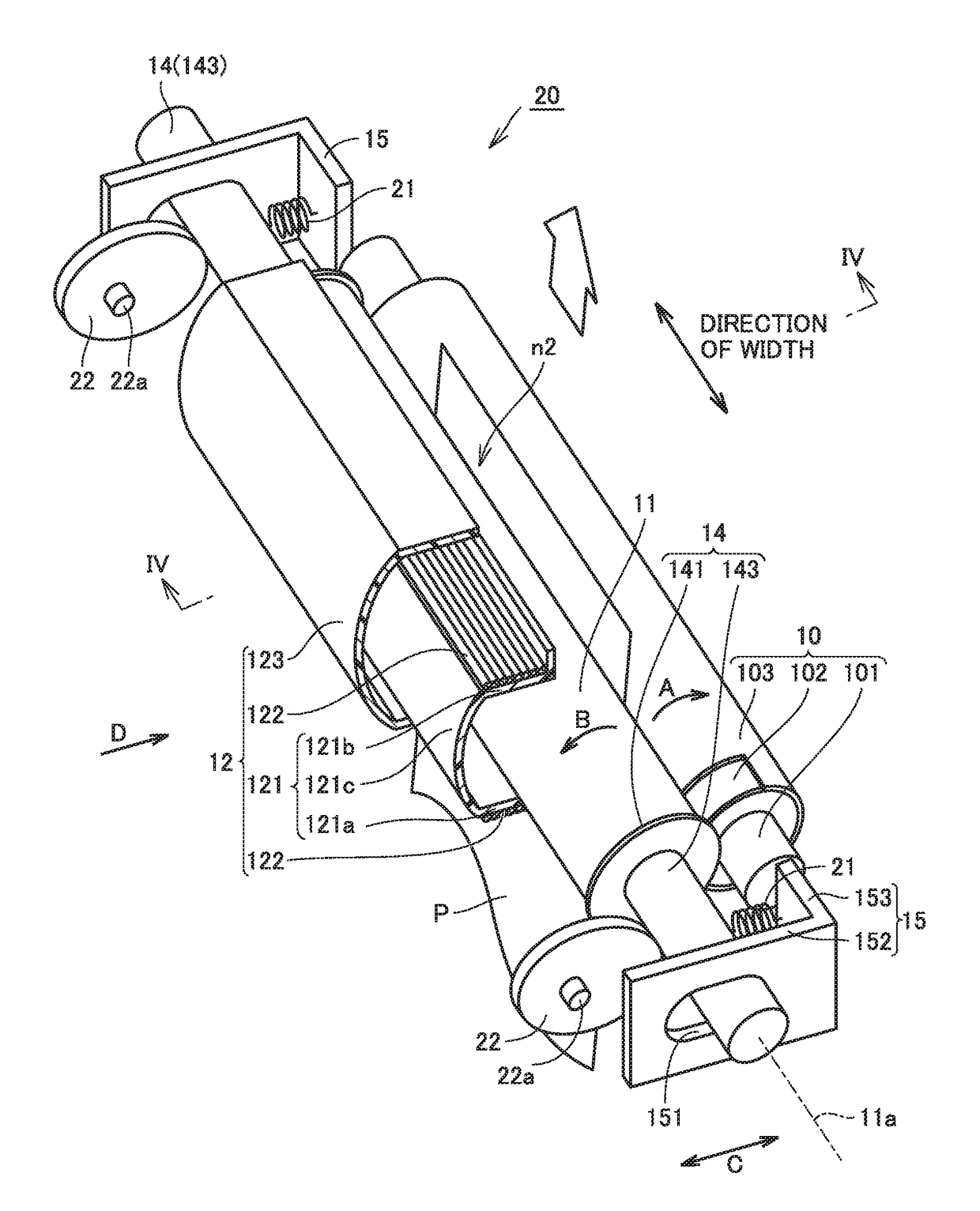
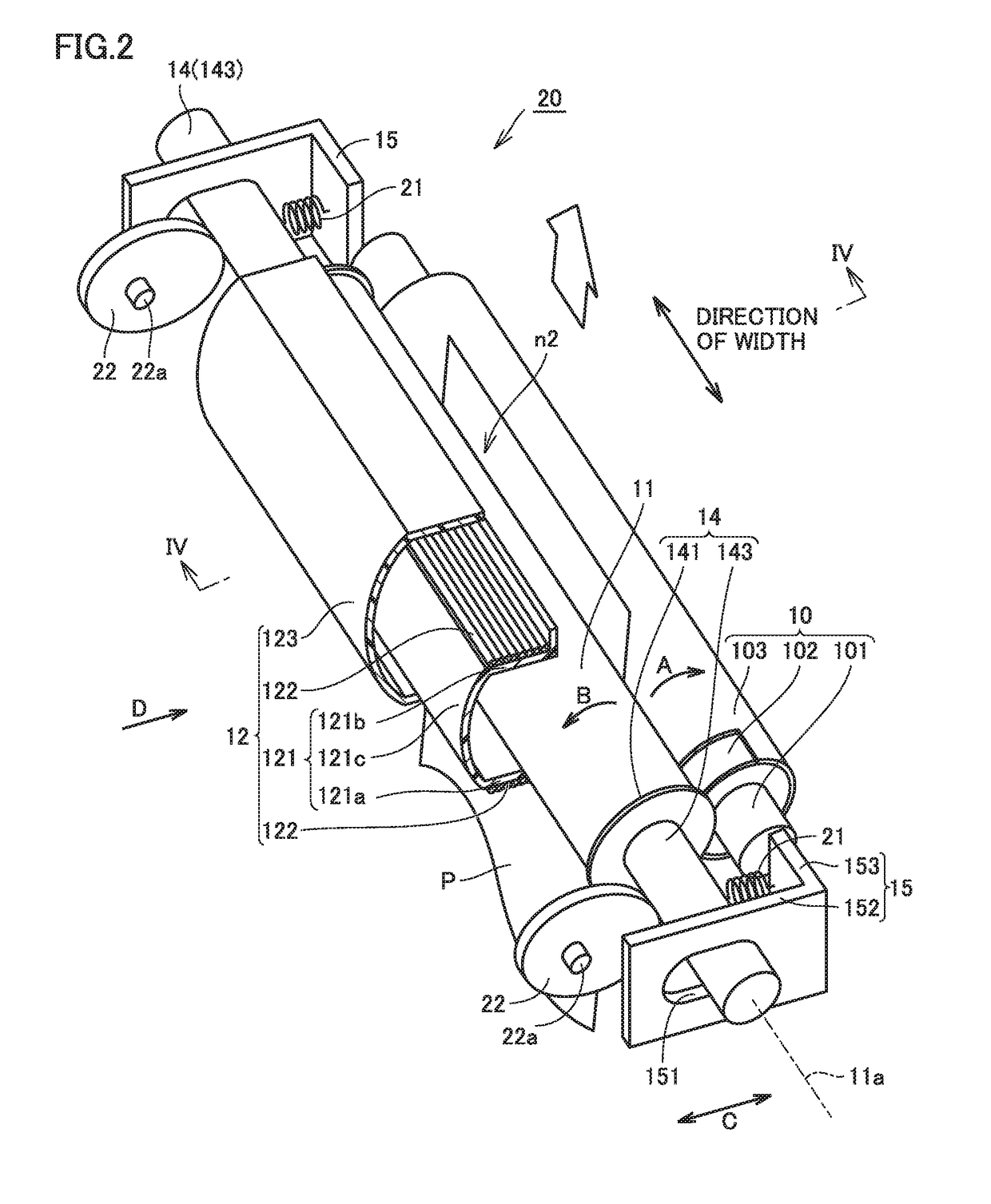
[0129]A fixing apparatus according to a second embodiment of the present disclosure will be described with reference to FIGS. 8A and 8B. FIG. 8A is a cross-sectional view showing a fixing apparatus 20A (in the fixing mode) according to the second embodiment FIG. 8B is a cross-sectional view showing fixing apparatus 20A (in the preheating mode) according to the second embodiment.

[0130]As shown in FIGS. 8A and 8B, fixing apparatus 20A is different from fixing apparatus 20 according to the first embodiment only in including a heating rotator 211 instead of heating rotator 1I and not including pressing member 16, first magnetic core 17, and second magnetic core 18 in the inside of heating rotator 211.

[0131]Heating rotator 211 is a cylindrical metal roller (cylinder) which is greater in thickness than heating rotator 11 and has sufficient strength. Therefore, it is not necessary to provide pressing member 16 inside heating rotator 211. Heating rotator 211 is composed, for example, of iro...

third embodiment

[0134]A fixing apparatus according to a third embodiment of the present disclosure will be described with reference to FIGS. 9, 10A, and 10B. FIG. 9 is a cross-sectional view showing an internal configuration of heating rotator 11 of a fixing apparatus 20B according to the third embodiment. FIGS. 10A and 10B are cross-sectional views showing fixing apparatus 20B according to the third embodiment. FIG. 10A shows a cross-sectional view at a position of a magnetic core 18c shown in FIG. 9 and FIG. 10B shows a cross-sectional view at a position of a magnetic core 18a shown in FIG. 9.

[0135]As shown in FIG. 9, fixing apparatus 20B according to the third embodiment is different from fixing apparatus 20 according to the first embodiment in including magnetic cores 18a to 18c instead of second magnetic core 18 and including support rods 26a to 26c connected to respective magnetic cores 18a to 18c in the inside of heating rotator 11.

[0136]Magnetic core 18a is arranged in a central portion in ...


PUM


Abstract

A fixing apparatus includes a heating rotator which generates heat with an induced current, an excitation coil arranged outside the heating rotator, a pressure roller which rotates with paper being held between the pressure roller and the heating rotator, the paper having a toner image developed thereon, and a relative position changer which changes a relative position of the excitation coil and the heating rotator to a first relative position when the toner image is being fixed to the paper and to a second relative position when the toner image is not being fixed to the paper. In a cross-section perpendicular to a rotation axis of the heating rotator, a distance from a point in an outer circumferential surface of the heating rotator closest to the pressure roller to the excitation coil is shorter at the second relative position than at the first relative position.

Description

[0001]The entire disclosure of Japanese Patent Application No. 2017-051160, filed on Mar. 16, 2017, is incorporated herein by reference in its entirety.BACKGROUNDTechnological Field[0002]The present disclosure relates to a fixing apparatus of an induction heating type and an image forming apparatus including the same.Description of the Related Art[0003]An image forming apparatus such as a copying machine includes a fixing apparatus for fixing a toner image transferred to paper onto the paper. An induction heating fixing apparatus including a heating rotator which melts toner, a pressure roller which presses paper by being brought in pressure contact with the heating rotator, and an excitation coil which heats the heating rotator has been known as the fixing apparatus.[0004]For example, Japanese Laid-Open Patent Publications Nos. 2011-53452 and 2016-24367 disclose a fixing apparatus in which an excitation coil is arranged inside a heating rotator.[0005]With arrangement of an excitati...

Claims


Application Information

Patent Timeline
IPC IPC(8): G03G15/20
CPCG03G15/2028G03G15/2053G03G15/2064G03G2215/2035
Inventor KANOU, HIROTAKA
Owner KONICA MINOLTA INC
Why Eureka
Try Eureka