Fixing device and image forming device

一种图像、加热辊的技术,应用在感应加热装置、应用电荷图形的电记录工艺、应用电荷图形的电记录工艺的设备等方向,能够解决不能够高精度地控制加热区域温度、检测灵敏度迟钝、加热辊冒烟等问题,达到良好快速复印性能的效果

Inactive Publication Date: 2009-01-21
SHARP KK
View PDF8 Cites 0 Cited by
  • Summary
  • Abstract
  • Description
  • Claims
  • Application Information

AI Technical Summary

Problems solved by technology

That is, when comparing position S1 and position S2, since the detection sensitivity of position S2 is slow, it can be seen that the temperature of the heating area near the induction coil cannot be controlled with high precision.
Therefore, if the temperature detection member is arranged at position S2 (non-heating area), the worst case is that the temperature of the heating area near the induction coil will rise abnormally, causing the risk of smoke and fire of the heating roller.
In addition, there are also cases where the heat-resistant temperature of the heating roller is exceeded, resulting in damage or degradation of the heating roller.
[0019] Here, with regard to the temperature control of the heating roller, the above-mentioned JP-A-10-104975 describes that the installation position of the temperature detection member is provided in the non-heating area, but when the temperature detection member is provided at this position, For the above reasons, it is difficult to heat the heating roller in a stopped state during standby, so the heating roller must be heated from room temperature every time an image is output, so that a good fast copying time cannot be obtained
Also, in the above-mentioned Japanese Patent Laid-Open No. 2002-72755, it is also described that a temperature detection member is provided in a non-heating region between the coils, but the vicinity between the coils is also a part where the generation of eddy current becomes smaller, thereby causing the same problem as above.

Method used


Image

  • Fixing device and image forming device
  • Fixing device and image forming device
  • Fixing device and image forming device

Examples


Embodiment Construction

[0070] Hereinafter, embodiments of the present invention will be described based on the drawings.

[0071] [A] Image forming device

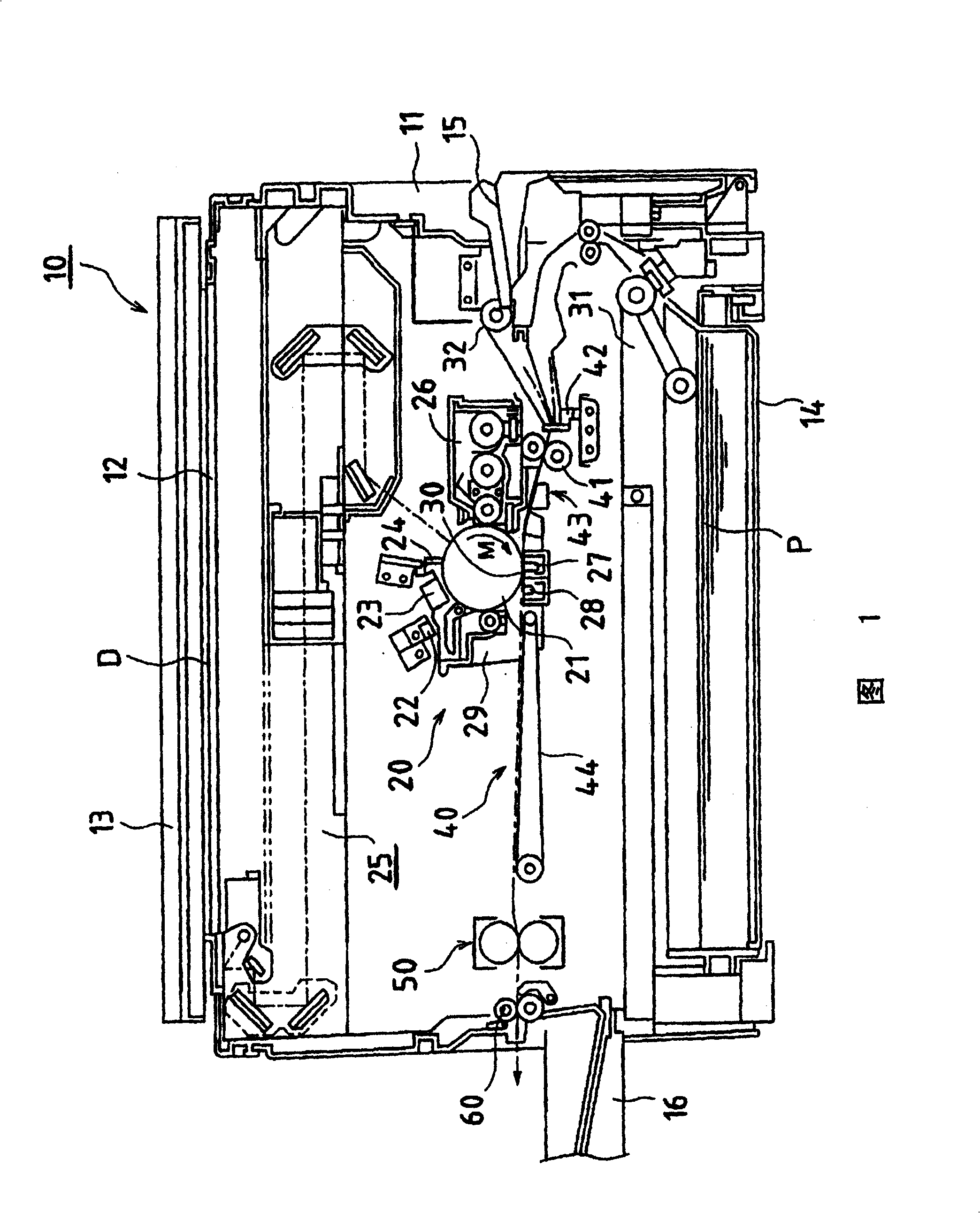
[0072] FIG. 1 is a cross-sectional view showing an example of an image forming apparatus of the present invention.

[0073] The image forming apparatus 10 shown in FIG. 1 is equipped with a housing-shaped apparatus main body 11, and an image forming apparatus for forming an image through image forming processes such as charging, exposure, development, transfer, and cleaning is disposed inside the apparatus main body 11. Section 20. Further, on the upper surface of the apparatus main body 11 , a platen glass 12 serving as a platen glass 12 and a platen cover 13 for pressing the document D placed on the platen glass 12 are provided.

[0074]A control panel (not shown) as an input / display unit is disposed on the front edge portion of the upper surface of the device main body 11 . Attached to the bottom of the apparatus main body 11 is a paper fe...


PUM


Abstract

A fixing device having a good fast-copy-out performance. The fixing device comprises a heating roller (1), a pressurizing roller (2), an induction coil (3a) for producing a magnetic flux, and a temperature detecting member (thermistor, etc) (5) for detecting the temperature of the heating roller (1). A magnetic flux produced by the induction coil (3a) produces an eddy current in the heating layer of the heating roller (1) to heat the roller (1) by induction heating. The temperature detecting member (5) is disposed in a area having a calorie of at least Q / e within the heating area of the roller (1), where Q is the maximum value of a calorie distribution in the heating area of the roller (1). A heating roller (1) temperature controlled based on a detection result by the temperature detecting member (5) prevents a heating roller (1) temperature from rising abnormally. While the fixing device is on stand-by, the roller (1) is heated while rotating.

Description

technical field [0001] The present invention relates to a fixing device for fixing a toner image on a recording material by heating and pressing, and an image forming apparatus using the fixing device. Background technique [0002] Conventionally, in electrophotographic image forming apparatuses, small-sized heating roller-type fixing devices capable of stable fixing have been widely used. Such a heating roller-type fixing device is configured as follows: a heating roller that heats and conveys a recording paper on which a toner image composed of powder developer (toner) is transferred; And convey the pressure roller of the recording paper, and make the recording material (paper) pass through the fixing point as the pressure contact portion (nip portion) between these heating rollers and the pressure roller, so that the toner image is melted and pressure-coated ( Fixing) on ​​the recording material. [0003] A heating method using a heater lamp is employed in a heating rol...

Claims


Application Information

Patent Timeline
Patent Type & Authority Patents(China)
IPC IPC(8): G03G15/20H05B6/14
CPCG03G15/2078G03G15/205
Inventor 山地博之
Owner SHARP KK
Why Eureka
Try Eureka