
Adjustable air-suction paper-feeding mechanism

An adjustable and air-feeding technology, which is applied in the field of suction paper feeding mechanism and adjustable suction paper feeding mechanism, can solve the problems of paper slipping, affecting the stability of paper conveying, and can't ensure the uniform distribution of suction air, so as to achieve saving The effect of wind power and stable transportation

Active Publication Date: 2016-02-10
YUTIAN DINGYU PRINTING MACHINERY MFG
View PDF8 Cites 4 Cited by
  • Summary
  • Abstract
  • Description
  • Claims
  • Application Information

AI Technical Summary

Problems solved by technology

[0002] Most of the suction and paper feeding mechanisms on the existing printing and packaging machinery use fans to directly connect with the air chamber plate and a bellows, and the air chamber plate is fixedly installed, so the air volume of the air suction hole and the switch of the air suction hole cannot be adjusted independently, and the suction air cannot be guaranteed. The uniform distribution of wind on the entire air chamber plate will easily cause the paper to slip on the belt and affect the stability of paper conveying, because the waste of suction and the small stress area of ​​the paper cannot stably convey small-sized paper

Method used


Image

  • Adjustable air-suction paper-feeding mechanism
  • Adjustable air-suction paper-feeding mechanism
  • Adjustable air-suction paper-feeding mechanism

Examples


Embodiment Construction

[0016] The present invention will be described in detail below in conjunction with the accompanying drawings.

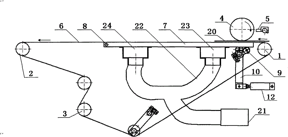
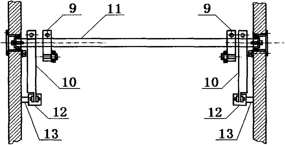
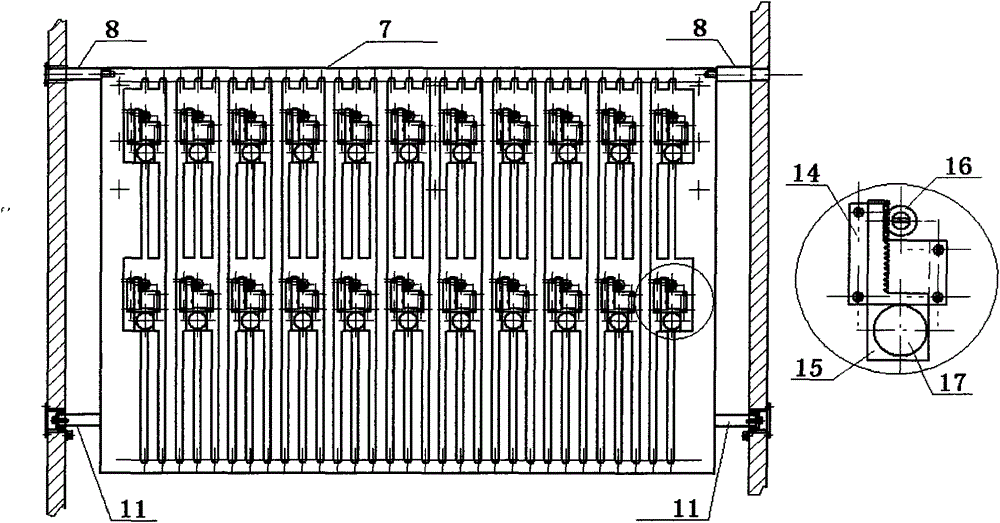
[0017] Such as Figure 1-4 As shown, the adjustable suction paper feeding mechanism includes a front belt roller 1, a rear belt roller 2, a driving roller 3, a photoelectric switch 4, a rubber roller 5, a suction belt 6, an air chamber plate 7, a bellows, a pin shaft 8, The top frame 9, the swing arm 10, the swing arm shaft 11, the cylinder 12, the air hole switch assembly, the two ends of the front belt roller 1, the rear belt roller 2, and the driving roller 3 are respectively arranged on the wall panels on both sides, and the photoelectric switch 5 is installed In front of the printing rubber roller 4, the suction belt 6 is wrapped on the front belt roller 1, the rear belt roller 2, and the driving roller 3. The air chamber plate 7 is arranged under the air suction belt 6. 1. In the last two rows of bellows, one end of the air chamber plate 7 is positioned on the...


PUM


Abstract

The invention discloses an adjustable air-suction paper-feeding mechanism. The adjustable air-suction paper-feeding mechanism comprises a front belt roller, a rear belt roller, a driving roller, a photoelectric switch, a printing rubber roller, an air-suction belt, an air chamber plate, air bellows, a hinge pin, top frames, swing arms, a swing arm shaft, cylinders and air hole switch assemblies. The two ends of the front belt roller, the two ends of the rear belt roller and the two sides of the driving roller are arranged on wall boards of the two sides respectively, the photoelectric switch is arranged in front of the printing rubber roller, the front belt roller, the rear belt roller and the driving rollers are wrapped with the air-suction belt, the air bellows of a front row and a rear row are installed below the air chamber plate, one end of the air chamber plate is positioned on the wall boards of the two sides, and the other end of the air chamber plate is arranged on the top frames; the top frames and the swing arms are fixed on the same swing arm shaft, the swing arm shaft is arranged on the wall boards of the two sides, the other end of the each swing arm is hinged to the corresponding cylinder, the cylinders are fixed on the wall boards of the two sides through fixing shafts, and the air hole switch assemblies are installed on the air chamber plate. According to adjustable air-suction paper-feeding mechanism, air suction is even, the air suction area and the air volume are adjustable, and rapid and stable conveying can be achieved whether paper is big or small.

Description

technical field [0001] The invention relates to a suction paper feeding mechanism, in particular to an adjustable suction paper feeding mechanism, which belongs to the field of printing and packaging machinery. Background technique [0002] Most of the suction and paper feeding mechanisms on the existing printing and packaging machinery use fans to directly connect with the air chamber plate and a bellows, and the air chamber plate is fixedly installed, so the air volume of the air suction hole and the switch of the air suction hole cannot be adjusted independently, and the suction air cannot be guaranteed. The uniform distribution of wind on the entire air chamber plate will easily cause the paper to slip on the belt and affect the stability of paper conveying. Because of the waste of suction and the small stress area of ​​the paper, it is impossible to convey small-sized paper stably. Contents of the invention [0003] In order to make the wind power of the suction paper...

Claims


Application Information

Patent Timeline
Patent Type & Authority Applications(China)
IPC IPC(8): B65H5/22B65H5/02
Inventor 宋学兵
Owner YUTIAN DINGYU PRINTING MACHINERY MFG
Learn More