Pipe-in-pipe buckle arrestor based on C and W type section deformation elements

A technology of deforming element and pipe-in-pipe, which is applied in pipeline laying and maintenance, pipe/pipe joint/pipe fitting, mechanical equipment, etc. Thermal insulation performance, efficient laying, and the effect of preventing relatively large movements

Inactive Publication Date: 2016-02-10
CHINA UNIV OF PETROLEUM (BEIJING)
View PDF5 Cites 0 Cited by
  • Summary
  • Abstract
  • Description
  • Claims
  • Application Information

AI Technical Summary

Problems solved by technology

However, when the pipe is pipe-in-pipe, the diameter increase on the outer pipe is unacceptable due to shipping and storage factors
[0011] Although the welded buckle arrester has a better buckle arrest effect than the snap-in type after welding, it is also prone to welding defects and stress concentration due to the existence of the weld seam
Integral buckle arrester with good buckling effect is suitable for deep water pipelines, but the welding process is more complicated, there are problems of weld stress concentration and welding defects caused by welding, and the economic cost is also higher than that of buckle-in buckle arrester device

Method used


Image

  • Pipe-in-pipe buckle arrestor based on C and W type section deformation elements
  • Pipe-in-pipe buckle arrestor based on C and W type section deformation elements
  • Pipe-in-pipe buckle arrestor based on C and W type section deformation elements

Examples


Embodiment Construction

[0024] The present invention will be described in detail below in conjunction with the accompanying drawings and embodiments.

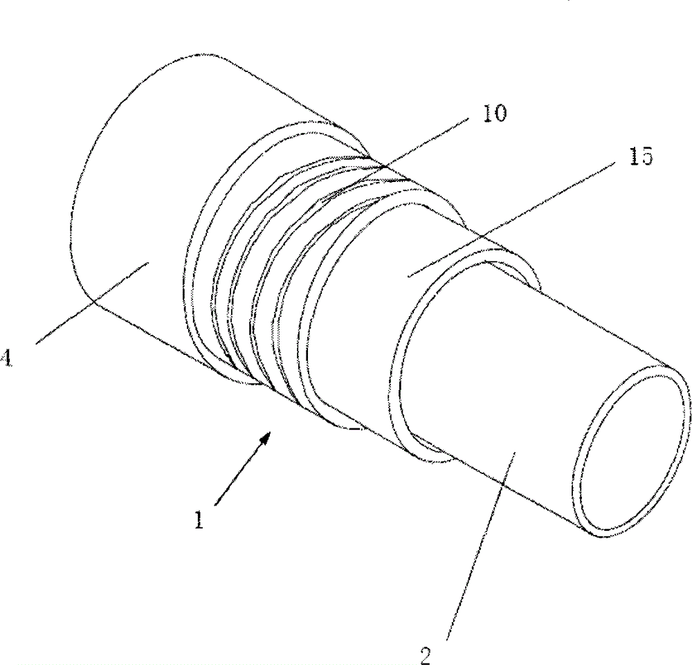
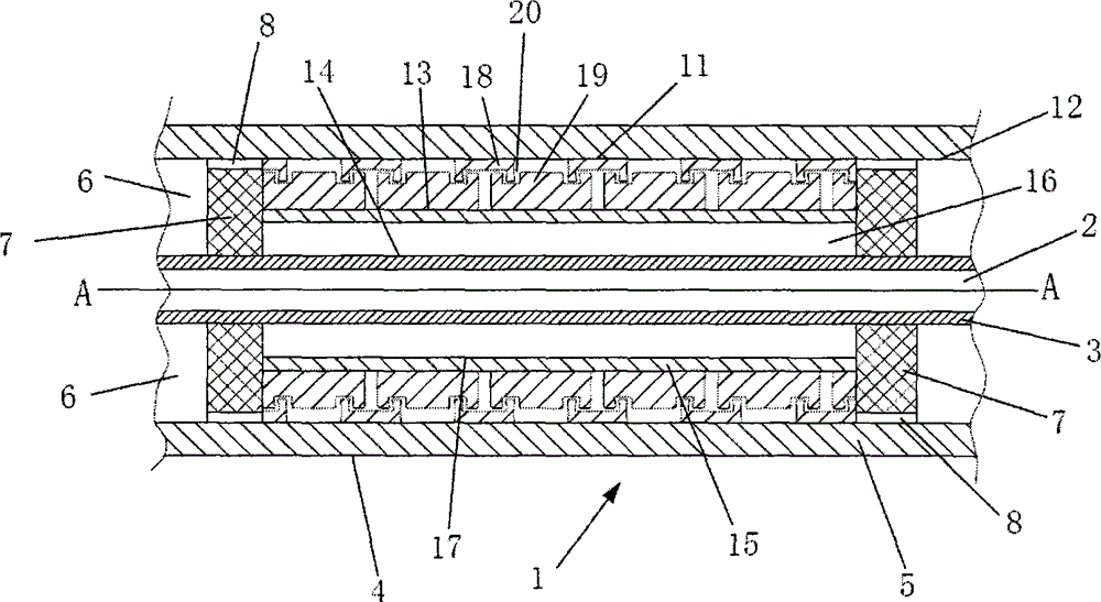
[0025] according to figure 1 and figure 2 As shown, in the present invention, the central axis of the rigid tube 1 is AA, and the rigid tube 1 is a tube-in-tube type, consisting of an inner tube 2 and an outer tube 4 . The pipe wall 3 of the inner pipe 2, the diameter and the material of the inner pipe 2 are determined according to the specific requirements of use.

[0026] The diameter of the outer tube 4 is large enough to allow the inner tube 2 to be inserted into it. The tube wall 5 of the outer tube 4 is sufficient to bear the pressure of the medium outside and around the rigid tube. There is an annular area 6 between the inner pipe 2 and the outer pipe 4, which is an annular area about several centimeters from the outer surface of the inner pipe 2 to the inner surface of the outer pipe 4 in the diameter direction. In the above-mentioned dou...


PUM


Abstract

The invention relates to a pipe-in-pipe buckle arrestor based on C and W type section deformation elements. The pipe-in-pipe buckle arrestor based on the C and W type section deformation elements is characterized in that the C and W type section deformation elements are additionally arranged between an inner pipe and an outer pipe of a pipe in pipe. The C type section deformation element and the W type section deformation element are buckled in the deformation process of pipe bending, the relative movement of the inner pipe and the outer pipe can be prevented from enlarging, and meanwhile the W section deformation element can play a role of resisting the internal pressure. The pipe-in-pipe buckle arrestor formed by the C and W type section deformation elements and a plastic shell, the size of the pipe in pipe does not need to be changed, the pipe-in-pipe buckle arrestor is directly installed between the inner tube and the outer pipe, and a heat insulating device in the pipe in pipes can not be affected. The buckle arrestor further has the universality, clipping can be conducted on the pipe in pipe with different sizes, a pipe in pipe manufacturer can directly install the buckle arrestor on the outer pipe, and the heat insulation property of the buckle arrestor can be further improved by selecting the plastic shell made of the heat insulation materials. According to the pipe-in-pipe buckle arrestor based on the C and W type section deformation elements, buckling and buckle propagation of a deep-water pipe in pipe in storing, installing and running can be prevented, installation of the deep-water pipe in pipe and the efficiency of arrest of buckle are improved, and the cost is reduced.

Description

technical field [0001] The invention belongs to the technical field of laying submarine pipeline facilities, and in particular relates to a method capable of preventing buckling propagation of submarine pipelines. Background technique [0002] With the increasing demand for oil and gas resources in countries all over the world, the development of submarine pipelines has become an irresistible trend. At the same time, there are many problems that need to be solved urgently in the design, construction and operation of submarine pipelines. The most prominent problem is the buckling of pipelines. The main reasons for buckling are: the joint action of elbows and external hydrostatic pressure, local depressions caused by collisions with other objects, and excessive bending during installation and use. Because the buckling propagation pressure is less than the local buckling pressure, once the local buckling instability occurs in the pipeline, the buckling will propagate along its ...

Claims


Application Information

Patent Timeline
IPC IPC(8): F16L1/20
Inventor 陈严飞夏梦莹刘啸奔张宏段庆全梁乐才陈金孝
Owner CHINA UNIV OF PETROLEUM (BEIJING)
Why Eureka
Try Eureka