
Optical structure, transparent display, side-projection display, mirror display and front-projection display

A technology of optical structure and optical microstructure, which is applied in the field of mirror and front projection display, optical structure and transparency, and side projection, which can solve the problems of unfavorable large-scale promotion, high price, and difficulty in manufacturing large-area transparent display materials.

Active Publication Date: 2016-02-10
杨文君
View PDF7 Cites 3 Cited by
  • Summary
  • Abstract
  • Description
  • Claims
  • Application Information

AI Technical Summary

Problems solved by technology

[0003] At present, the common transparent display screen is OLED screen, which is transparent, soft and bendable, but the price is relatively high, and the production area cannot be very large. It is generally used in the screens of digital devices such as mobile phones.
In terms of manufacturing, this technology is also difficult to manufacture large-area transparent display materials, which is not conducive to large-scale promotion

Method used


Image

  • Optical structure, transparent display, side-projection display, mirror display and front-projection display
  • Optical structure, transparent display, side-projection display, mirror display and front-projection display
  • Optical structure, transparent display, side-projection display, mirror display and front-projection display

Examples


no. 1 example

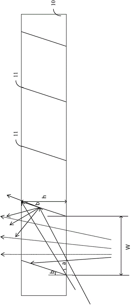
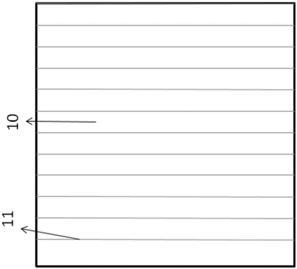
[0067] refer to Figure 1a and Figure 1b , Figure 1a and Figure 1b A first example of an optical structure is shown, including: a light-transmitting film 10 and a plurality of optical microstructures 11 disposed in the light-transmitting film 10 .

[0068] Wherein, the material of the light-transmitting film 10 may be various materials that allow light to pass through, and the light-transmitting film 10 may be transparent or translucent, and so on.

[0069] The front of each optical microstructure 11 forms a predetermined angle with the surface of the light-transmitting film 10 . There are intervals between adjacent optical microstructures 11 . The front side of the optical microstructure 11 scatters or reflects the incident light, that is, the light incident on the front side of the optical microstructure 11 will be scattered or reflected, while the light not incident on the front side of the optical microstructure 11 will directly pass through. The light-transmitting f...

no. 6 example

[0087] refer to Figure 10 , Figure 10 A sixth example of a transparent display screen is shown, including: a light-transmitting film 90 , a plurality of optical microstructures 91 disposed in the light-transmitting film 90 , and a medium 92 bonded on one side of the light-transmitting film 00 . Figure 10 The sixth example shown with Figure 5 The structure of the transparent display screen in the first example shown is basically the same, the difference is that in the sixth example, one side surface of the medium 92 (the surface attached to the light-transmitting film 90 ) has a variety of film layers with different refractive indices in different regions. 921 , for example, has film layers 921 with refractive indices n4, n5 and n6 according to different regions. In addition, one surface of the medium 92 (the surface attached to the light-transmitting film 90 ) may also have an anti-reflection film or an anti-reflection film. The other surface of the medium 92 may also h...


PUM


Abstract

The invention provides an optical structure, a transparent display, a side-projection display, a mirror display and a front-projection display. The optical structure comprises a light-transmitting film and multiple optical microstructures arranged in the light-transmitting film, wherein the front side of each of the multiple optical microstructures and the surface of the light-transmitting film form a preset angle, the adjacent optical microstructures are spaced apart, and the front sides of the optical microstructures scatter or reflect the incident light. According to the invention, multiple display modes such as transparent display can be realized with low cost, and the optical structure is easy to manufacture.

Description

technical field [0001] The invention relates to an optical structure and transparent, side projection, mirror surface and front projection display screens. Background technique [0002] With the development of display technology, various types of display screens emerge in an endless stream, such as LCD display screens, LED display screens, and the like. In addition, currently various display screens with special display effects have also received widespread attention, one of which is a transparent display screen. [0003] At present, the common transparent display screen is OLED screen, which is transparent, soft and bendable, but the price is relatively high, and the production area cannot be very large. It is generally used in the screens of digital devices such as mobile phones. In terms of manufacturing, this technology is also difficult to manufacture large-area transparent display materials, which is not conducive to large-scale promotion. Contents of the invention ...

Claims


Application Information

Patent Timeline
IPC IPC(8): G02B5/08G02B5/02
Inventor 杨磊
Owner 杨文君
Learn More