Accurate positioning of a timepiece bar or bridge

A bridge bridge and splint technology, which is applied in the field of accurate positioning of the clock bar splint or bridge bridge, and can solve the problems of changing the safety, efficiency and loss of the escapement mechanism

Active Publication Date: 2016-02-10
MONTRES BREGUET
View PDF7 Cites 7 Cited by
  • Summary
  • Abstract
  • Description
  • Claims
  • Application Information

AI Technical Summary

Problems solved by technology

In the specific case of a lever escapement, a change in the position of the pallet changes the distance between the center and the neutral line, which directly changes the safety, efficiency and losses of the escapement

Method used


Image

  • Accurate positioning of a timepiece bar or bridge
  • Accurate positioning of a timepiece bar or bridge
  • Accurate positioning of a timepiece bar or bridge

Examples


Embodiment Construction

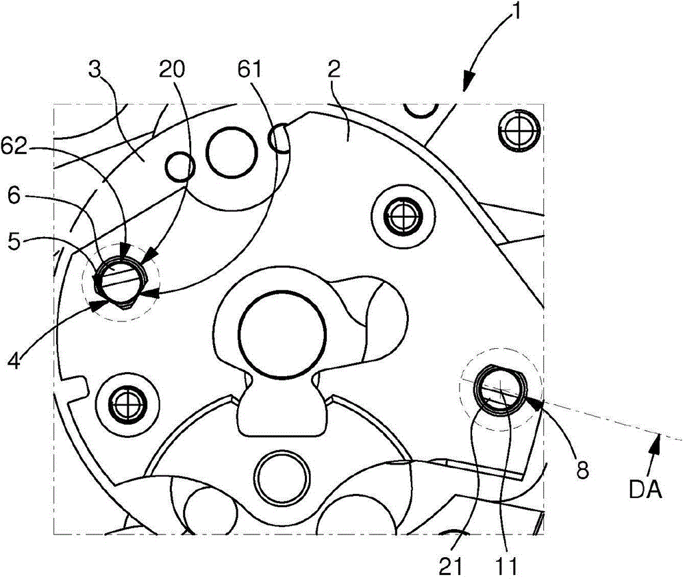
[0034] The invention proposes to define, for a timepiece mechanism or movement, a bar-on-plate assembly that ensures positioning accuracy and alignment accuracy and allows disassembly by pushing out the element and once the positioning element is pushed in again can be repositioned perfectly reproducibly.

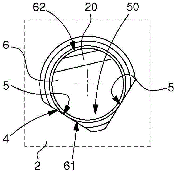
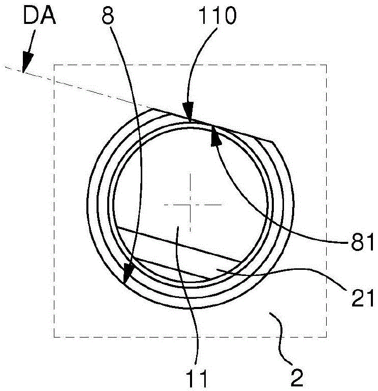
[0035] The invention thus relates to a removable timepiece assembly 1 comprising at least one bar bridge 2, at least one main plate 3, and for each such bar bridge a first centering pin 6 and a second centering pin 6. Align pin 11.

[0036] The splint 2 is arranged to be positioned on the motherboard 3 by a first centering pin 6 comprising a first outer peripheral surface 60 and a second alignment pin 11 , and the first centering pin 6 and the second alignment pin 11 are arranged to cooperate with both the main board 3 and the bar clamp 2 .

[0037]According to the invention, at least the main plate 3 or the main plate 2 comprises first female centering means 4 for the re...


PUM


Abstract

The invention relates to a detachable timepiece assembly (1), which comprises a bar or bridge (2) positioned on a bar-on-plate (3) through a first centering pin (6) and a second aligning pin (11). The first centering pin and the second aligning pin are in cooperation with the bar-on-plate (3) and the bar or bridge (2). The bar-on-plate (3) or the bar or bridge (2) includes a first female centering device (4) for relative centering and a gap occupying device (20). The first female centering device receives the first pin (6) by abutting against two first facets (5) forming a dihedral edge (50). The gap occupying device is configured to apply direct or indirect force to the first pin (6). The invention also relates to an escapement mechanism including the detachable assembly, a timepiece movement including the escapement mechanism, and a timepiece comprising the movement.

Description

technical field [0001] The present invention relates to a removable timepiece assembly comprising at least one bar, bridge or bridge arranged to be positioned on a main plate by means of a first centering pin and a second alignment pin, said first The centering pin includes a first outer peripheral surface, the first centering pin and the second alignment pin are included in the assembly and arranged to cooperate with both the main plate and the bar clamp, wherein at least the The main plate or said main plate comprises female centering means for the relative centering of said bar and said main plate, the female centering means comprising dihedral edges forming parallel to the joining direction and said first female means is arranged to receive said first pin on said two facets in an abutting manner by a first portion of said first peripheral surface of said first pin a pin, and wherein said assembly includes first gap-occupiers arranged so that, when said first pin is in pos...

Claims


Application Information

Patent Timeline
Patent Type & Authority Applications(China)
IPC IPC(8): G04B29/02G04B15/14G04B33/00
CPCG04B29/02G04B29/04
Inventor D·曼金S·马莱夏B·朱诺
Owner MONTRES BREGUET
Why Eureka
Try Eureka