
conductive electrode

A technology of conductive electrodes and conductive substrates, which is applied in the input/output process of electrical digital data processing, instruments, and data processing, etc., can solve the problem of side erosion of metal conductive electrodes 10, large wire diameter impedance values ​​of electrode lines 14, and reduce conductive electrodes. Product yield and other issues to achieve the effect of reducing severe side erosion

Active Publication Date: 2018-08-03
APLUS SEMICON TECH CO LTD
View PDF5 Cites 0 Cited by
  • Summary
  • Abstract
  • Description
  • Claims
  • Application Information

AI Technical Summary

Problems solved by technology

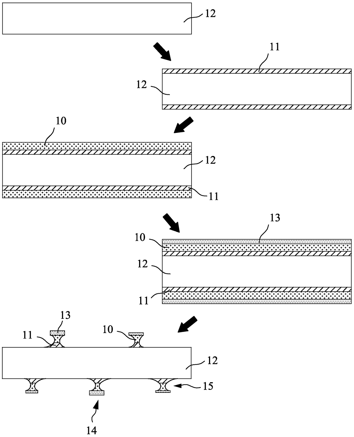
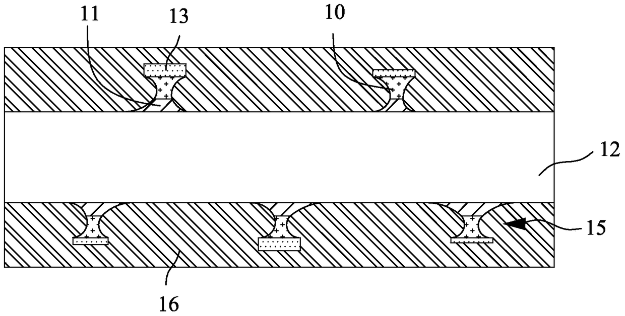
[0007] To further illustrate, the electrode line 14 structure of the conventional sensing electrode (Sensor) is protected through a weather-resistant layer 13 with an etching resistance property, which can be used as a conductive metal conductive electrode 10. When an etching process is performed, Wet etching is isotropic (Isotropic), and because the weather-resistant layer 13 is an etching-resistant material, the etching rate difference between the weather-resistant layer 13 and the metal conductive electrode 10 for the etching liquid is very large, and for the step ( 2) The distribution of the formed weather-resistant layer 13 is usually a non-uniform thickness. Therefore, when the etching solution is used for longitudinal etching, a serious side erosion phenomenon 15 may occur on the metal conductive electrode 10 during the etching process.
[0008] see again figure 1 As shown, in other words, that is, the left and right sides of the metal conductive electrode 10, especially the wire diameter of the metal conductive electrode 10 whose width is designed to be less than 5 μm and whose thickness is designed to be greater than 0.3 μm, is more prone to side erosion phenomenon 15 , resulting in an excessively large proportion of the total etched area of ​​the metal conductive electrode 10, and an excessively large impedance value of the electrode line 14 wire diameter caused by uneven etching, and what is more, a disconnection of the electrode line 14 occurs, which makes the manufacturer's The yield and quality of the metal conductive electrodes 10 produced are not easy to control, which is actually a fundamental problem in the development and production of ultra-thin conductive electrodes.
[0009] Based on the deficiency of the metal conductive electrode 10 for the aforementioned touch panel, the present invention aims to prevent the existence of the conductive electrode from being clearly noticed by the user with the eyes, and to improve the side etching phenomenon 15 of the conductive electrode caused by the conventional conductive electrode. The wire diameters of different sizes will eventually reduce the yield rate of conductive electrode products, which is actually the purpose of the present invention.

Method used


Image

  • conductive electrode
  • conductive electrode
  • conductive electrode

Examples


Embodiment Construction

[0044] In order to further have a clearer and more detailed understanding and understanding of the structure, use and features of the present invention, a preferred embodiment is given, and the details are as follows in conjunction with the drawings:

[0045] see Figure 4A to Figure 4B As shown, in a preferred embodiment of the conductive electrode for touch control of the present invention, the manufacturing steps are described as follows.

[0046] (A) select a preset base material, form a base material layer 2 by the base material, the base material layer 2 can be made of soft material or glass plate, and the soft material is made of poly Polyethylene terephthalate (PET), polymethyl methacrylate (PMMA), polycarbonate (PC), polyphenylene sulfone (PPSU), polyethyleneimine (PEI) or polyimide ( PI) made of one of them;

[0047] (B) At least one conductive adhesion layer 3 is formed on the surface of the base material layer 2, wherein the thickness of the adhesion layer 3 is b...


PUM

PropertyMeasurementUnit
thicknessaaaaaaaaaa
thicknessaaaaaaaaaa
thicknessaaaaaaaaaa

Abstract

The invention relates to a conductive electrode which comprises a substrate layer, at least one attaching layer, a conductive electrode layer, a first blackening layer and a weather-proof layer; the attaching layer is provided with a line pattern laid on the surface of the substrate layer, the conductive electrode layer is formed on the surface of the attaching layer and forms a conductive line corresponding to the line pattern, the first blackening layer is formed on the surface of the conductive electrode layer and made of materials easy to etch, and the weather-proof layer is formed on the surface of the first blackening layer and made of the materials easy to etch; the thickness of the weather-proof layer is smaller than that of the first blackening layer, and the first blackening layer is made of dark-colored materials, so that light rays are absorbed by the first blackening layer and cannot enter the conductive electrode layer to form a shielding surface through which a user can be prevented from directly seeing the conductive electrode layer. Accordingly, the conductive electrode can achieve the purposes of preventing the human eyes from directly seeing the conductive electrode arranged under a touch panel, reducing the phenomenon that the conductive electrode is laterally etched and improving the production yield of conductive electrode products.

Description

technical field [0001] The invention relates to a conductive electrode, especially a conductive electrode made of an easily etched blackened layer and an extremely thin weather-resistant layer, which reduces the phenomenon of light interference fringes caused by the wires of the conductive electrode and increases The user sees the comfort of the product, and at the same time greatly reduces the side erosion phenomenon in the manufacturing process, thereby achieving a stable wire diameter of the conductive electrode. Background technique [0002] With the development of electronic information products in the direction of thinner, lighter and smaller, the semiconductor manufacturing method is also moving towards the direction of high-density and automatic production. Or the size of the touch panel product gradually increases from small to large, and the material of the conductive electrode is changed from the commonly used indium tin oxide (ITO) to the metal conductive electro...

Claims


Application Information

Patent Timeline
Patent Type & Authority Patents(China)
IPC IPC(8): G06F3/041
Inventor 赖玉豪
Owner APLUS SEMICON TECH CO LTD
Learn More