
Light emitting module and display device

A light-emitting module and display device technology, which is applied in the direction of lighting devices, fixed lighting devices, semiconductor devices of light-emitting elements, etc., can solve the problems of display device 1 such as lowered display quality and moiré, so as to improve display quality and reduce interference fringes Effect

Inactive Publication Date: 2016-04-06
INNOCOM TECH (SHENZHEN) CO LTD +1
View PDF7 Cites 0 Cited by
  • Summary
  • Abstract
  • Description
  • Claims
  • Application Information

AI Technical Summary

Problems solved by technology

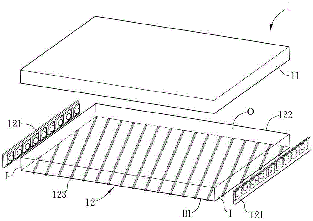
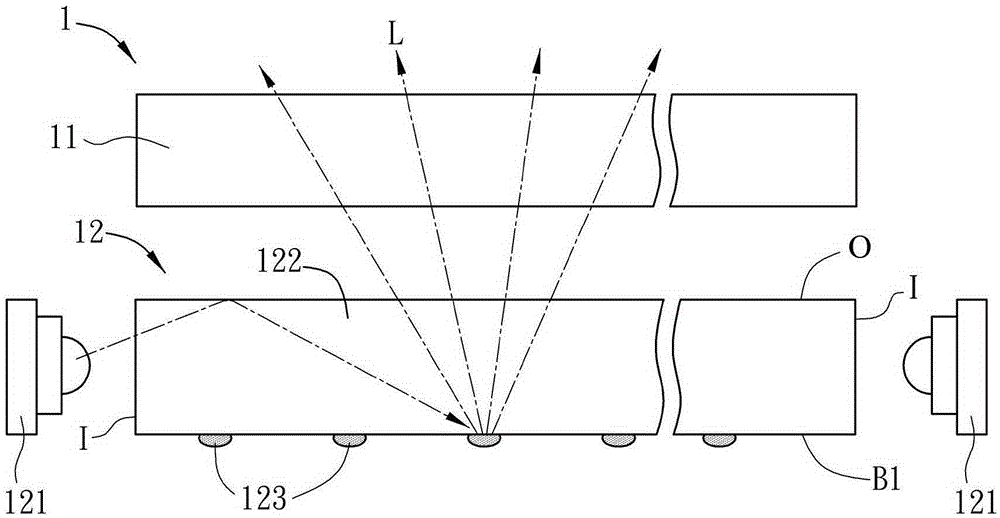
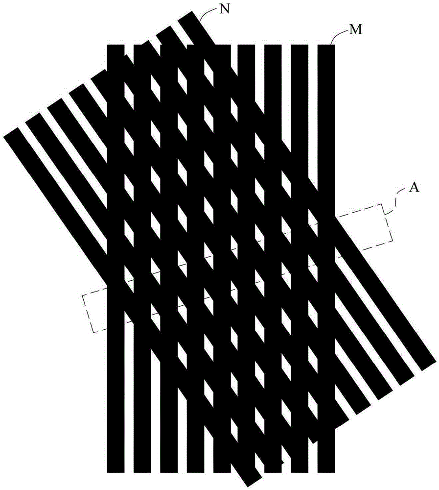
[0006] However, when the light L is emitted from the light-emitting surface O of the light guide plate 122, the light on the light-emitting surface O is in the form of oblique straight lines arranged alternately with bright and dark intervals. , opaque, not shown in the figure), such as Figure 1C shown in area A ( Figure 1C The linear stripes M shown in the figure are formed by the light L passing through the light-shielding layer, and the oblique stripes N are formed by the light and dark staggered oblique straight rays on the light-emitting surface O of the light guide plate 122), which will make the light emitted from the display panel 11 appear optically Interference fringes appear due to the interference phenomenon of diffraction ( Figure 1C Only one interference fringe is marked in the area A, and the rest are not marked), that is, the phenomenon commonly known as moire (Moiré) occurs, resulting in a decrease in the display quality of the display device 1

Method used


Image

  • Light emitting module and display device
  • Light emitting module and display device
  • Light emitting module and display device

Examples


Embodiment Construction

[0058] A light emitting module and a display device according to preferred embodiments of the present invention will be described below with reference to related drawings, wherein the same elements will be described with the same reference symbols.

[0059] Please refer to Figure 2A , Figure 2B and Figure 2C As shown, among them, Figure 2A and Figure 2B are respectively a three-dimensional schematic view and a side view schematic view of a display device 3 in a preferred embodiment of the present invention, and Figure 2C for Figure 2A , the corresponding schematic diagram of the sub-pixels of the display panel 4 and the light guide elements. hereby, Figure 2A to Figure 2C It is only for illustration and does not show the actual scale of the object. Also, for clarity, Figure 2C Only the sub-pixels of the display panel 4 , the light guide plate 21 and the light guide elements are shown, and other components of the display panel 4 are not shown.

[0060] The dis...


PUM


Abstract

The invention provides a light-emitting module. The light-emitting module is used in cooperation with a display panel, and the display panel has a plurality of pixels. The light-emitting module comprises a light guide plate, a plurality of light guide elements and a light-emitting unit, wherein the light guide plate can guide the direction of light, and is provided with at least one light incident face and two opposite side faces, the light guide elements are arranged on one of the side faces of the light guide plate, the light guide elements are arranged corresponding to the pixels in a one-to-one mode, a user can observe the light guide elements in the direction perpendicular to the side face with the light guide elements, the overhead view area of each light guide element is larger than zero and smaller than the area of the pixel corresponding to the light guide element, the light-emitting unit is arranged on the light incident face of the light guide plate, after the light emitted by the light-emitting unit enters the light guide plate, the light is guided through the light guide plate and the light guide elements, and the light can be guided out through one of the side faces of the light guide plate in a bright-and-dark alternate arrangement mode. By the adoption of the light-emitting module, the frequency of the phenomenon of interference fringes of optical diffraction can be reduced, and display quality of a display device is improved.

Description

technical field [0001] The present invention relates to lighting equipment technology, in particular to a light emitting module and a display device. Background technique [0002] In recent years, due to continuous improvements in technology and materials of light emitting diodes (Light Emitting Diodes, LEDs), the luminous efficiency of light emitting diodes has been greatly improved. Different from ordinary fluorescent lamps or energy-saving light bulbs, LEDs have the characteristics of low power consumption, long service life, high safety, short luminous response time and small size, so they are gradually used in lighting equipment, light boxes or light-emitting modules. Among them, the lighting equipment is, for example, indoor and outdoor lamps, flashlights, headlights and taillights of automobiles and motorcycles, or other lighting devices, and the light emitting module can be used as a backlight module of a display device or other purposes. [0003] Please refer to F...

Claims


Application Information

Patent Timeline
Patent Type & Authority Patents(China)
IPC IPC(8): F21S8/00F21V8/00G02B27/22F21Y115/10
Inventor 杨仁智潘政晟黄大晋康宙煜朱谱錞
Owner INNOCOM TECH (SHENZHEN) CO LTD
Learn More