
A tool and replacement method for replacing fan unit body in the field

A replacement method and unit body technology, applied in the field of aero-engines, can solve the problems of rotor stator scraping and inability to replace the working blades of the fan unit body, and achieve the effect of avoiding returning to the factory for repair, ensuring the use rate and saving cycles.

Active Publication Date: 2017-08-18
SHENYANG LIMING AERO-ENGINE GROUP CORPORATION
View PDF7 Cites 0 Cited by
  • Summary
  • Abstract
  • Description
  • Claims
  • Application Information

AI Technical Summary

Problems solved by technology

[0002] At present, aero-engines cannot replace the fan unit body and the working blades of the subsequent stage in the field. When the fan unit body is separated, the compressor and the turbine rotor are separated, and the axial position of the rotor stator changes. When reassembling, the rotor stator may be scraped.

Method used


Image

  • A tool and replacement method for replacing fan unit body in the field
  • A tool and replacement method for replacing fan unit body in the field

Examples


Embodiment

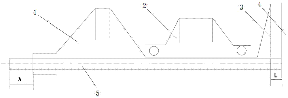
[0024] Example: such as figure 1 , figure 2 As shown, the present invention includes a positioning rod 5 and a baffle plate 6, and the positioning rod 5 is provided with an adjustable baffle plate 6. During use, the positioning rod 5 is placed in the low-pressure rotor 1, the high-pressure rotor 2 and the low-pressure turbine rotor of the engine. , one end of the positioning rod 5 is in contact with the rear fulcrum bearing housing 4, the other end is close to the side of the engine intake cap cover, the adjusting baffle 6 is placed on the end face of the low-pressure rotor shaft, the measuring end face 7 of the measuring baffle 6 is in contact with the end face of the positioning rod 5 The distance A between.

[0025] The baffle plate 6 is connected to the positioning rod 5 through locking screws.

[0026] Or the baffle plate 6 is connected with the positioning rod 5 through a slider chute and fixed by a pin.

[0027] Such as figure 1 , figure 2 As shown, the method fo...


PUM


Abstract

The invention discloses a tool for replacing a fan unit body on outfield and a replacing method. The tool comprises a positioning rod and a baffle. The positioning rod is provided with an adjustable baffle. When the tool is used, the positioning rod is located in a low-pressure rotor, a high-pressure rotor and a low-pressure turbine rotor; one end of the positioning rod makes contact with a rear-fulcrum bearing shell body, and the other end of the positioning rod is close to gas inlet cap cover side of an engine; the end face used for measuring of the baffle is adjusted to be on the axial end face of the low-pressure rotor, and the distance A between the end face used for measuring of the baffle and the end face used for stopping of the positioning rod is measured. According to the tool for replacing the fan unit body on the outfield and the replacing method, blade replacing on the outfield is achieved, so that the depot repair of the engine is avoided and the repair cost is reduced; about two million can be saved of each engine, and the period is shortened, so that the using availability rate of the engine on the outfield is ensured.

Description

technical field [0001] The invention belongs to the technical field of aero-engines, in particular to a tool for replacing a fan unit in the field. Background technique [0002] At present, aero-engines cannot replace the fan unit body and the working blades of the subsequent stage in the field. When the fan unit body is separated, the compressor and the turbine rotor are separated, and the axial position of the rotor stator changes. When reassembling, the rotor stator may be scraped. . Contents of the invention [0003] Aiming at the above-mentioned technical problems, the present invention provides a tool for replacing the fan unit in the field. When the fan unit is replaced and assembled in the field, the axial dimension of the engine rotor is ensured by the axial positioning of the special tool. [0004] The invention indirectly guarantees the assembly technical requirements of the rotor-stator axial dimension by analyzing the engine structure, principle and assembly ...

Claims


Application Information

Patent Timeline
Patent Type & Authority Patents(China)
IPC IPC(8): B25B27/00
CPCB25B27/00
Inventor 李春波包宏强王丹
Owner SHENYANG LIMING AERO-ENGINE GROUP CORPORATION
Learn More