
Vibration theory based manifold thermal shield support mounting positioning method

A technology of installation positioning and heat shield, applied in the direction of electrical digital data processing, special data processing applications, instruments, etc., can solve theoretical analysis and research, the installation and positioning position of the connecting bracket still stays, and the welding part of the connecting bracket is easy to break, etc. problem, to achieve the effect of solving the problem of location layout, avoiding returning to the factory for repair, and avoiding irrationality

Inactive Publication Date: 2017-06-13
无锡红湖消声器有限公司
View PDF1 Cites 0 Cited by
  • Summary
  • Abstract
  • Description
  • Claims
  • Application Information

AI Technical Summary

Problems solved by technology

For each specific manifold, heat shield, and heat shield support, it has its own natural frequency as a whole. When these natural frequencies are close to the excitation frequency output by the engine, the manifold assembly will occur. Resonance, if the mounting position of the connecting bracket is such that it is at the peak of the mode shape, then the welding part of the connecting bracket is easy to break
At present, the major manufacturers' research on preventing the breakage of the connecting bracket between the engine manifold and the heat shield is mainly focused on optimizing the shape of the heat shield bracket, and has not specifically analyzed and studied the welding position of the bracket. The installation and positioning position of the connecting bracket still stays on the installation and positioning requirements based on the space position. With the determination of the shape of the heat shield support, that is, the determination of its own vibration mode frequency and mode shape, and the limitation of the space position, the connection The problem of bracket fracture is difficult to overcome by optimizing the shape of the heat shield bracket

Method used


Image

  • Vibration theory based manifold thermal shield support mounting positioning method
  • Vibration theory based manifold thermal shield support mounting positioning method
  • Vibration theory based manifold thermal shield support mounting positioning method

Examples


Embodiment Construction

[0022] The specific implementation manners of the present invention will be further described in detail below in conjunction with the accompanying drawings and embodiments. The following examples are used to illustrate the present invention, but are not intended to limit the scope of the present invention.

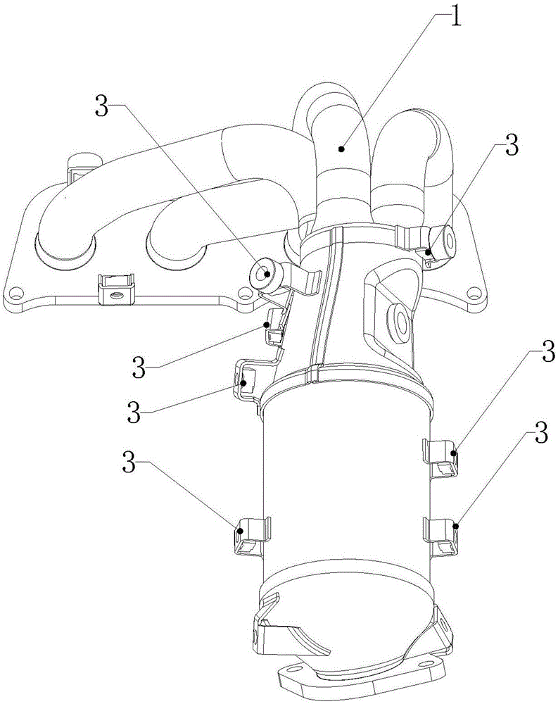
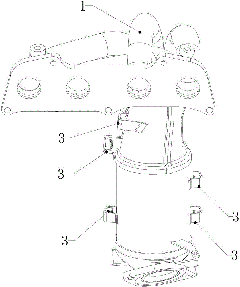
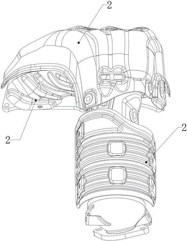
[0023] see Figure 1 to Figure 3 According to a preferred embodiment of the present invention, a method for installing and positioning a manifold heat shield bracket based on vibration theory includes the following steps:

[0024] S1: Arrange multiple collection points on the exhaust manifold 1, conduct modal analysis on the exhaust manifold through the hammering method, and obtain the modal frequency of each mode of the exhaust manifold and the modal frequency The corresponding mode shapes;

[0025] S2: According to the ADDOFD method, calculate the value x corresponding to the characteristic displacement of each acquisition point at each modal frequency r ,which is:

...


PUM


Abstract

The invention relates to a vibration theory based manifold thermal shield support mounting positioning method. The method includes: by exhaust manifold modal experiments, arranging a plurality of acquisition point positions on objects as many as possible, and performing modal analysis to extract modal frequencies and modal shapes corresponding to the modal frequencies; calculating according to an ADDOFD (average driving degrees of freedom displacement) method to obtain values corresponding to acquisition point characteristic displacements; performing weighted displacement method calculation according to weights to obtain a point position minimum in displacement in welding of a connection support and a thermal shield. Thermal shield supports welded according to the vibration theory based manifold thermal shield support mounting positioning method are less prone to breakage off the manifolds.

Description

technical field [0001] The invention relates to a method for installing and positioning a manifold heat shield bracket, in particular to a method for installing and positioning a manifold heat shield bracket based on vibration theory. Background technique [0002] The manifold heat shield is generally installed on the manifold through a connecting bracket. One end of the connecting bracket is connected to the heat shield bracket with bolts, and the other end is welded on the surface of the manifold body. For each specific manifold, heat shield, and heat shield support, it has its own natural frequency as a whole. When these natural frequencies are close to the excitation frequency output by the engine, the manifold assembly will occur. Resonance, if the mounting position of the connecting bracket is such that it is at the peak of the mode shape, then the welding of the connecting bracket is easy to break. At present, the major manufacturers' research on preventing the break...

Claims


Application Information

Patent Timeline
Patent Type & Authority Applications(China)
IPC IPC(8): G06F17/50
CPCG06F30/17G06F30/20
Inventor 张凤
Owner 无锡红湖消声器有限公司
Learn More