

Organic electroluminescent cell, packaging method thereof, and coater station thereof
A technology of electroluminescent components and packaging methods, applied in electrical components, electroluminescent light sources, electric light sources, etc., can solve the problems of reducing the manufacturing cycle of components and the placement of water-removing agents, so as to reduce the manufacturing cycle of components and promote Hygroscopic ability, effect of reducing component manufacturing cost
- Summary
- Abstract
- Description
- Claims
- Application Information
AI Technical Summary
Problems solved by technology
Method used
Image

Examples
no. 1 example
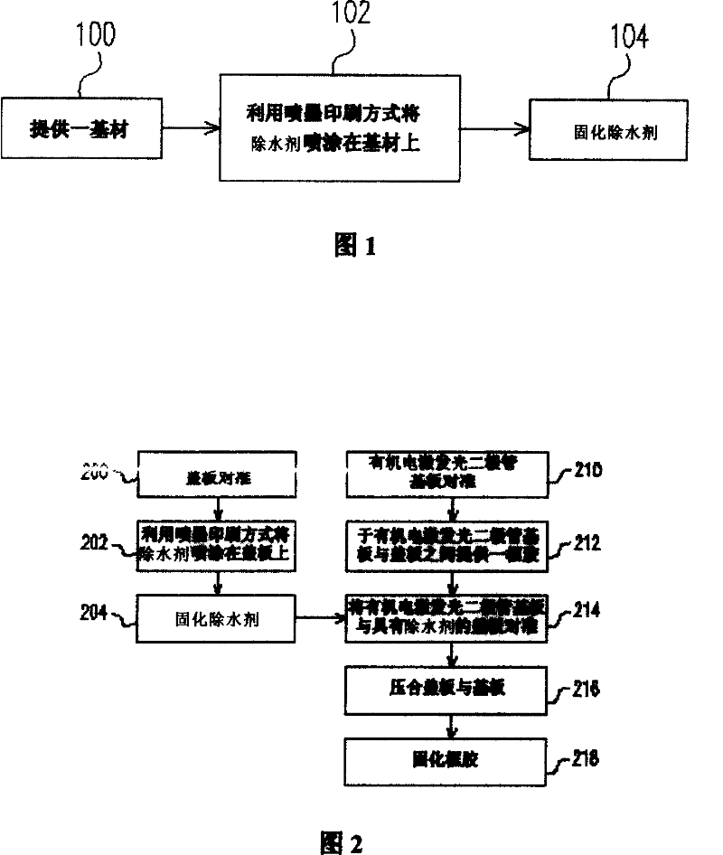
[0044] FIG. 1 is a schematic diagram of the steps of spraying a dewatering agent according to a first embodiment of the present invention.
[0045] Referring to FIG. 1 , in step 100 , a substrate is provided, wherein the substrate can be a plane or a substrate with grooves. Then, in step 102, inkjet printing is used to spray desiccant on the substrate. In this embodiment, more than one inkjet head or similar device can be used to directly print A water remover with a high surface area pattern is sprayed on it, and the water remover can be sprayed on a flat substrate or a substrate with grooves, and the water remover can be thermosetting or UV curing. Next, proceed to step 104, curing the water-removing agent; if the water-removing agent is a thermosetting type, then curing the water-removing agent is performed by heating; if the water-removing agent is an ultraviolet curing type, then curing the water-removing agent is performed by a Appropriate wavelength, appropriate time o...
no. 2 example
[0048]The invention can be applied in the process of display elements and light source elements of organic electroluminescent elements. In this embodiment, the present invention is applied to the packaging process of organic electroluminescent elements, as shown in FIG. 2 . Mainly, the preparation of the cover part and the preparation of the organic light emitting diode (OLED for short) substrate are carried out separately, and then the two are combined to achieve the packaging process of the components.
[0049] FIG. 2 is a schematic diagram of packaging steps of an organic electroluminescence device according to a second embodiment of the present invention.
[0050] In step 200, the alignment of the cover is to align an inkjet head or similar device for performing inkjet printing with the cover, wherein the cover can be flat or grooved glass, plastic or Flexible substrate. Then, in step 202, inkjet printing is used to spray the dewatering agent on the cover plate. This ste...
no. 3 example
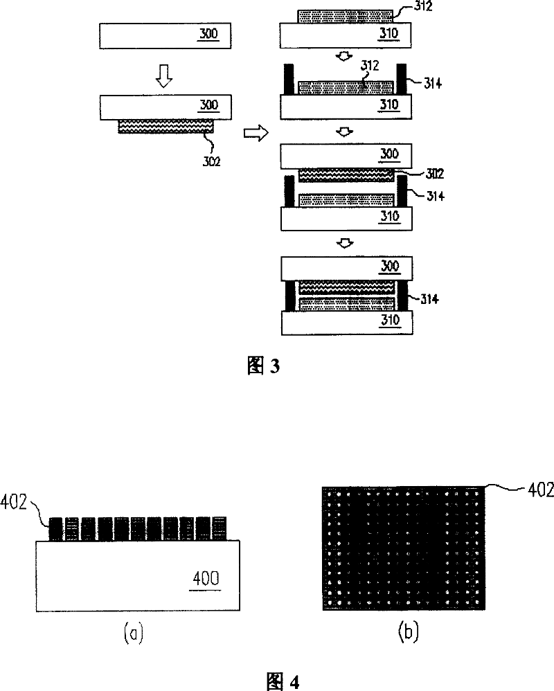
[0056] The present invention also proposes an organic electroluminescent element, which can greatly increase the surface area of the dewatering agent to shorten the curing time of the dehydrating agent and increase the moisture absorption capacity of the dehydrating agent. In order to simplify the diagram, only the relative positions of the cover plate and the water remover in the organic electroluminescent element of the present invention are shown in FIG. 4 , and the structure after the cover plate and the organic electroluminescent element substrate are packaged refers to the previous FIG. 3 shown.
[0057] 4 is a schematic cross-sectional and top view of the cover plate and the water remover in an organic electroluminescent device according to a third embodiment of the present invention. Please refer to (a) of FIG. 4 , there is a layer of pattern on a cover plate 400 Chemical water remover 402. This layer of dehydrating agent 402 is inkjet printing, so that the shape of...
PUM
 Abstract
Description
Claims
Application Information