
A sight locking device

A technology of locking device and sight, which is applied in the direction of supporting machines, mechanical equipment, machines/brackets, etc., can solve the problems of reducing the reliability of the mechanism, unable to lock, and increasing the production and processing costs, so as to reduce the production and processing costs, The number of special parts is small, and the effect of enhancing the anti-loosening effect

Active Publication Date: 2017-06-13
HEBEI HANGUANG HEAVY IND
View PDF6 Cites 0 Cited by
  • Summary
  • Abstract
  • Description
  • Claims
  • Application Information

AI Technical Summary

Problems solved by technology

[0003] Conventional scope locking devices only use thread locking. Even if anti-loose glue is applied, it is still prone to loosening after repeated use. If it is found in time, it can continue to be locked, but it is time-consuming and laborious; The locking product falls off from the locking bracket, resulting in damage to the product and easy injury to personal safety;
[0004] Although the locking effect of the conventional scope locking device is relatively ideal, the structure is complex and the number of parts is large, which reduces the reliability of the entire mechanism and increases the production and processing costs;
[0005] When the conventional scope locking device is locked, it needs to pull the wrench several times to lock it, and the operation is laborious, and it cannot be locked quickly. If the structure of the wrench is unreasonable and it is used for a long time, the wrench may slip, cannot be locked, and will not be used.

Method used


Image

  • A sight locking device
  • A sight locking device
  • A sight locking device

Examples


Embodiment Construction

[0027] The present invention will be described in detail below with reference to the accompanying drawings and examples.

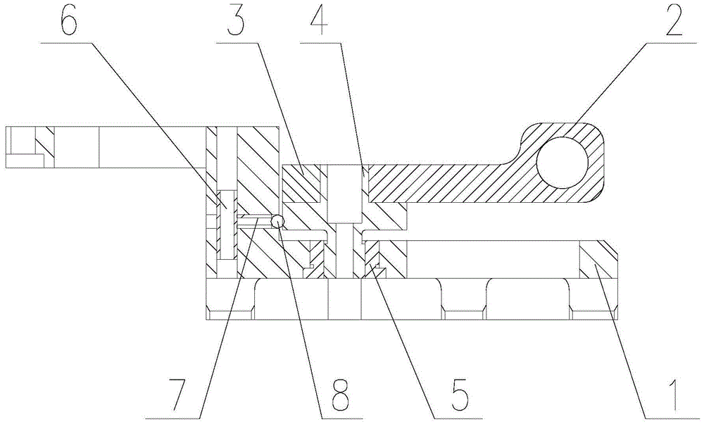
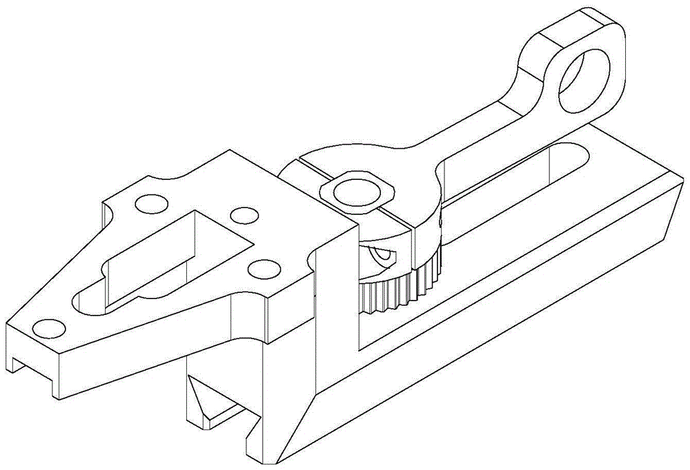
[0028] The invention provides a sight locking device, see the attached Figure 1-2 , including: adapter seat 1, wrench 2, locking ring 3, lock screw 4, lock nut 5, cotter pin 6, compression spring 7 and ball 8;

[0029] See attached Figure 3-4 , the adapter seat 1 is a ladder-type bracket, and the ladder-type bracket is composed of an upper plate, a lower plate and a vertical plate; the upper plate of the ladder-type bracket has a mounting hole connected to the sight; the vertical bracket of the ladder-type bracket There are vertical holes and horizontal holes perpendicular to each other on the plate, wherein the axis of the vertical hole is parallel to the plane where the vertical plate is located; the bottom surface of the lower plate of the stepped bracket is provided with a dovetail groove connected to the gun, and the lower plate The upper part is ...


PUM


Abstract

The invention discloses a locking device for a sighting telescope, and belongs to the technical field of connecting and locking of sighting telescopes. The locking device comprises an adapter, a wrench, a locking ring, a stop screw, a locknut, a cotter pin, a pressure spring and a ball, wherein the locknut is fixed on a lower slab of the adapter; a small cylindrical section of the stop screw is in threaded connection with the locknut; a hollow cylinder formed after the wrench is in butt joint with the locking ring sleeves a square cylinder section of the stop screw, and is used for locking the wrench and the locking ring through the stop screw; the cotter pin is mounted in a vertical hole of a vertical plate of the adapter, and penetrates a horizontal hole in the vertical plate of the adapter; the ball is mounted in the horizontal hole of the adapter; and one end of the ball is propped against circumferential teeth of the stop screw, and the other end of the ball is propped against the cotter pin through the pressure spring. The locking device can be used for locking the sighting telescope reliably, safely, quickly and effortlessly.

Description

technical field [0001] The invention belongs to the technical field of scope connection and locking, and in particular relates to a scope locking device. Background technique [0002] In order to realize that all products such as scopes and cameras that need to be locked with the bracket can be used during work, transportation, and even high-intensity vibration and impact without loosening, a high-reliability scope locking device is required. [0003] Conventional scope locking devices only use thread locking. Even if anti-loose glue is applied, it is still prone to loosening after repeated use. If it is found in time, it can continue to be locked, but it is time-consuming and laborious; The locking product falls off from the locking bracket, resulting in product damage and easy injury to personal safety; [0004] Although the locking effect of the conventional scope locking device is relatively ideal, the structure is complex and the number of parts is large, which reduces...

Claims


Application Information

Patent Timeline
Patent Type & Authority Patents(China)
IPC IPC(8): F16M11/04
CPCF16M11/04
Inventor 李世荣李晓雷周立媛
Owner HEBEI HANGUANG HEAVY IND
Learn More