
A Method of Simultaneously Compensating the Scale Factor and Zero Bias of Fiber Optic Gyroscope Using a Temperature Experiment

A technology of scaling factor and compensating optical fiber, which is applied in the direction of measuring devices, instruments, etc., to achieve the effect of saving experiment cost and time, high cost, and avoiding inaccurate compensation

Active Publication Date: 2018-02-23
HUBEI SANJIANG AEROSPACE HONGFENG CONTROL
View PDF5 Cites 0 Cited by
  • Summary
  • Abstract
  • Description
  • Claims
  • Application Information

AI Technical Summary

Problems solved by technology

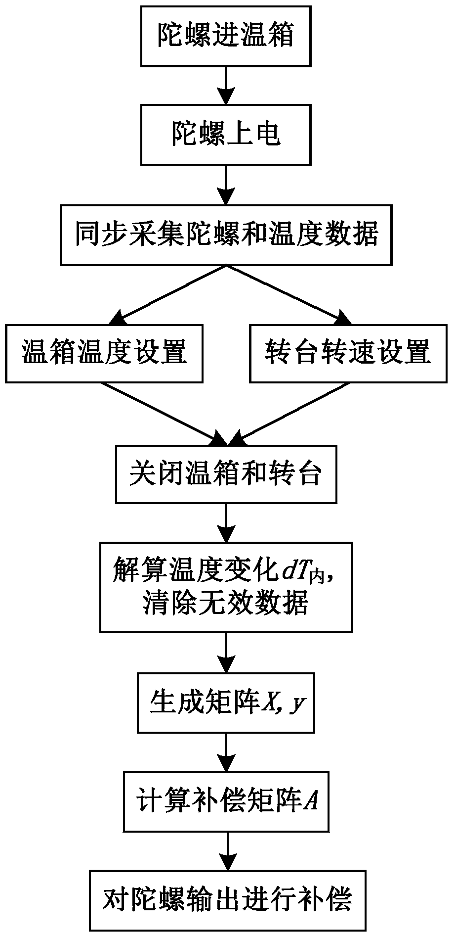
[0004] Aiming at the defects of the existing compensation methods, the present invention provides a method for compensating the scale factor and zero bias of the fiber optic gyroscope at the same time by using a temperature experiment. The purpose is to effectively compensate the errors of the scale factor and zero bias caused by temperature, and reduce the Experimental cost, improved accuracy of compensation

Method used

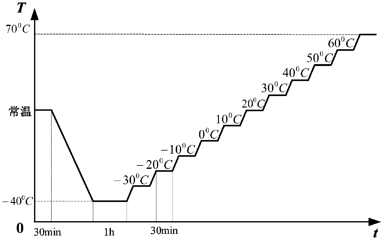
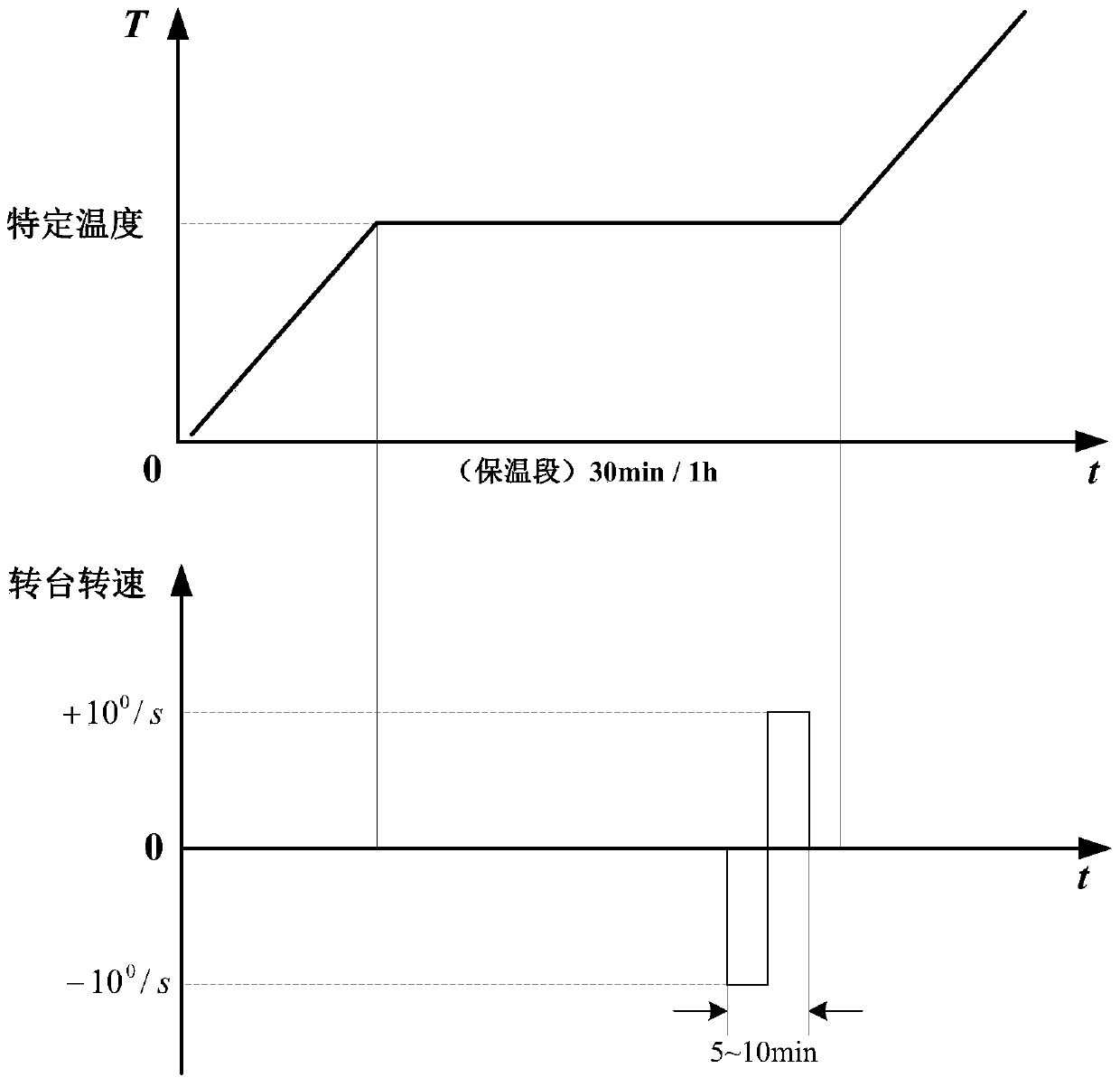

Image

  • A Method of Simultaneously Compensating the Scale Factor and Zero Bias of Fiber Optic Gyroscope Using a Temperature Experiment
  • A Method of Simultaneously Compensating the Scale Factor and Zero Bias of Fiber Optic Gyroscope Using a Temperature Experiment
  • A Method of Simultaneously Compensating the Scale Factor and Zero Bias of Fiber Optic Gyroscope Using a Temperature Experiment

Examples


Embodiment Construction

[0036] In order to make the objectives, technical solutions, and advantages of the present invention clearer, the following further describes the present invention in detail with reference to the accompanying drawings and examples. It should be understood that the specific embodiments described herein are only used to explain the present invention, but not to limit the present invention.

[0037] The compensation method proposed in the present invention is designed to simultaneously compensate the scale factor and zero offset in a temperature experiment, directly express the relationship between the digital output of the gyro and the input angular velocity, obtain the compensation coefficient matrix, and avoid the scale factor compensation caused by the zero offset error. The inaccuracy not only can effectively compensate the temperature error of the gyro, but also saves the cost and time of the experiment, which has great practical significance.

[0038] The purpose of the present...


PUM


Abstract

The invention discloses a method for simultaneously compensating a scale factor and a zero offset of an optical fiber gyroscope by a one-time temperature experiment. The method comprises the following steps: (1) adjusting the temperature of an incubator, rotating the gyroscope clockwise and anticlockwise when the temperature reaches respective set temperature values, and acquiring temperature data acquired by a temperature sensor in the gyroscope in real time and data which correspond to the temperature and are output by the gyroscope in the whole process of switching on and switching off the incubator; (2) processing the temperature data and the data output by the gyroscope according to a simultaneous scale factor and zero offset compensation algorithm, and obtaining a temperature compensation coefficient matrix; (3) compensating the output of the gyroscope according to the temperature compensation coefficient matrix. According to the compensation method provided by the invention, the one-time temperature experiment is designed to simultaneously compensate the scale factor and the zero offset of the optical fiber gyroscope; a relation between a digital value output by the gyroscope and an input angle speed is directly expressed, so that the compensation coefficient matrix is obtained; therefore, the inaccuracy, which is caused by a zero offset error and the like, of compensation of the scale factor is avoided; furthermore, the temperature error of the gyroscope can be effectively compensated, and the method can save the experiment cost and is higher in practical significance.

Description

Technical field [0001] The invention belongs to the field of fiber optic gyroscopes, and more specifically, relates to a method for simultaneously compensating the scale factor and zero offset of the fiber optic gyroscope using a temperature experiment. Background technique [0002] Fiber optic gyroscope is an angular rate sensor based on the Sagnac effect. Due to its low cost, simple process, high reliability, and strong resistance to shock and vibration, its application prospects have attracted much attention and have become one of the mainstream sensors. However, the main components of fiber optic gyroscopes, such as fiber optic rings and light sources, are sensitive to temperature, which causes the output of fiber optic gyroscopes to be greatly affected by temperature, resulting in gyroscope temperature errors. Therefore, the compensation of fiber optic gyroscope temperature errors has attracted widespread attention. [0003] The temperature compensation of the fiber optic gyro...

Claims


Application Information

Patent Timeline
Patent Type & Authority Patents(China)
IPC IPC(8): G01C25/00
CPCG01C25/00
Inventor 孙娜高枫姜见龙
Owner HUBEI SANJIANG AEROSPACE HONGFENG CONTROL
Learn More