A negative pressure array centrifugal gas electrospinning device

A gas electrospinning and air supply device technology, applied in textiles and papermaking, filament/thread forming, and clustering of newly extruded filaments, etc., can solve the difficulties of forming three-dimensional structures, low efficiency of electrospinning, and difficulties in three-dimensional structures etc. to achieve the effects of low cost, simple structure of the device, and enhanced controllability of the airflow path

A gas electrospinning and air supply device technology, applied in textiles and papermaking, filament/thread forming, and clustering of newly extruded filaments, etc., can solve the difficulties of forming three-dimensional structures, low efficiency of electrospinning, and difficulties in three-dimensional structures etc. to achieve the effects of low cost, simple structure of the device, and enhanced controllability of the airflow path

CN105350093BInactive Publication Date: 2018-04-17GUANGDONG UNIV OF TECH

Image

  • A negative pressure array centrifugal gas electrospinning device
  • A negative pressure array centrifugal gas electrospinning device
  • A negative pressure array centrifugal gas electrospinning device

Examples


Embodiment 1

[0046] The negative pressure array centrifugal gas electrospinning device disclosed in the present invention, when used, first prepares the spinning solution, weighs 1800 mg of PLLA (molecular weight = 200,000 Daltons), dissolves it in 30 ml (9:1, CH 2 Cl 2 / DMF, v / v) solvent, prepared 6% PLLA solution, sealed with parafilm, magnetically stirred for 3 hours, and set aside.

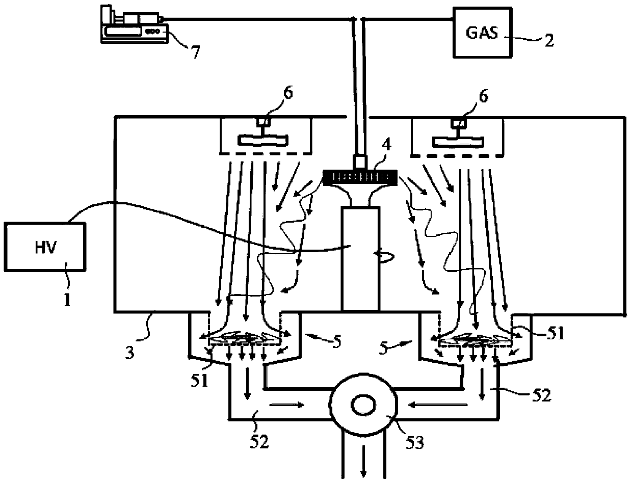
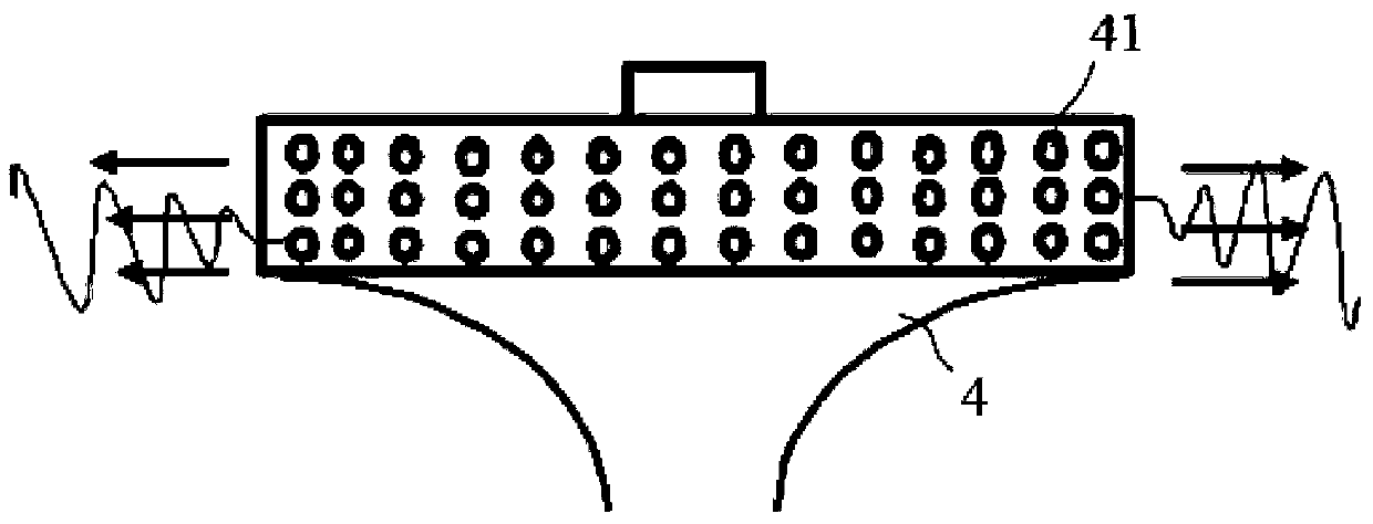
[0047] Fill the liquid supply device 7 with PLLA solution, open the liquid supply device 7, the flow rate is 1mL / min, open the gas supply device 2, adjust the air pressure to 0.75MPa, open the negative pressure receiving device 5, and then turn on the switch of the adjustable speed DC motor 83 , the rotation speed is 5000rpm, so that the PLLA solution at the outlet fine hole 41 forms a continuous jet under the action of centrifugal force and air flow. Under the airflow guidance of the device 6, a large number of three-dimensional nano PLLA fiber scaffolds are collected on the negative pressure receiving ...

Embodiment 2

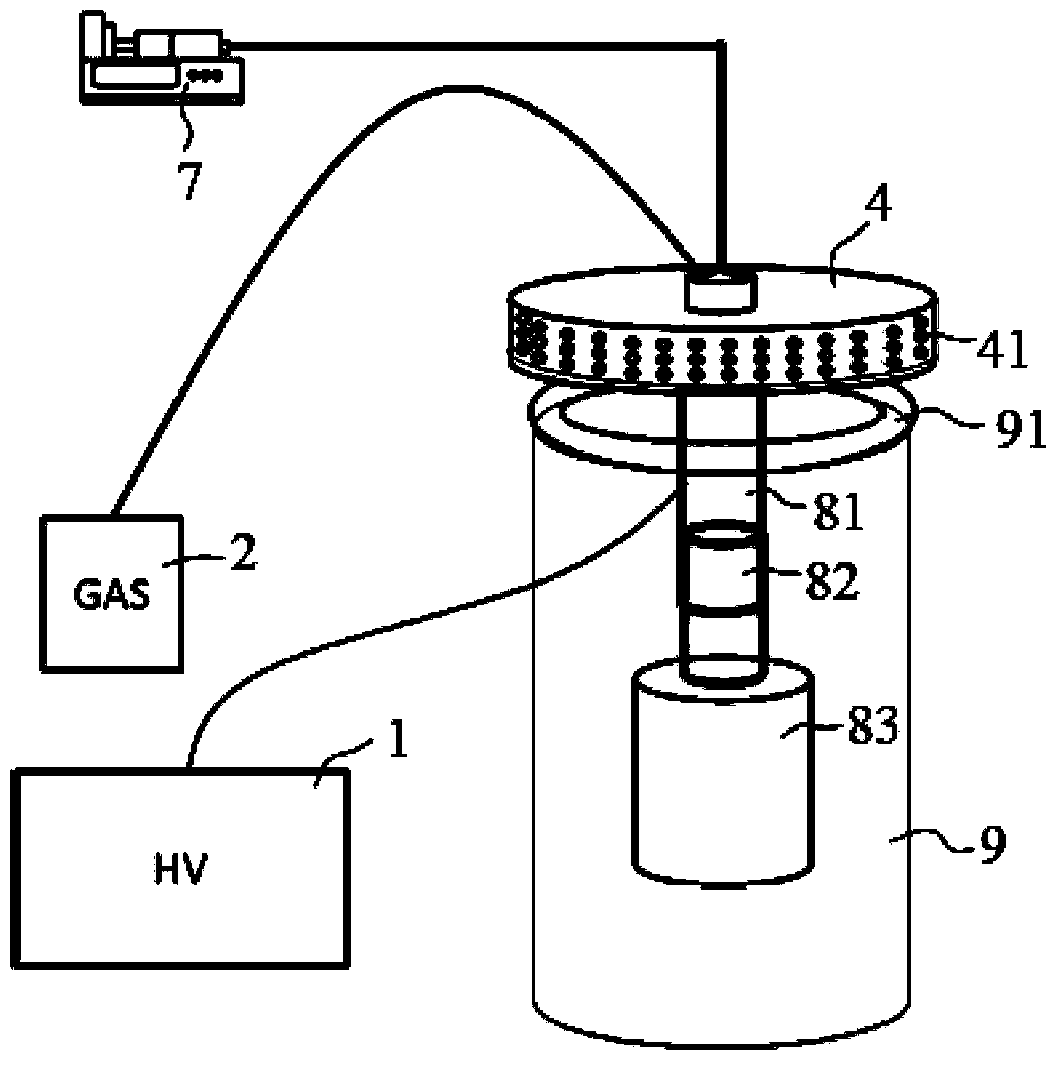
[0049] The negative pressure array centrifugal gas electrospinning device disclosed by the present invention uses polylactic acid as a raw material during use, adds 20 grams of polylactic acid into the feed port, and then turns on the switch of the heating device 91 to heat the polylactic acid in the centrifugal nozzle 4 to In the molten state, open the negative pressure receiving device 5, open the gas supply device 2, adjust the air pressure to 0.8MPa, open the switch of the adjustable-speed DC motor 83, and the rotation speed is 6000rpm, so that the centrifugal force of the polylactic acid melt at the 41 places of the filament pores , form a continuous jet under the action of the air flow, and the jet is through thinning and evaporation processes, and under the action of the electric field force, the negative pressure suction of the negative pressure receiving device 5 and the airflow guidance of the blower device 6, a large amount of water is collected on the negative pressu...


PUM


Abstract

The invention discloses a negative pressure array centrifugal gas electrospinning device, which comprises a high-voltage AC generator, an air supply device, a box body, a centrifugal nozzle, a centrifugal driving mechanism and a negative pressure receiving device. The nozzle is provided with a fine hole for the filament, and the negative pressure receiving device includes a collector, a negative pressure tube and a negative pressure generator. The negative pressure tube forms a negative pressure nozzle at the bottom of the box, and the collector is nested in the negative pressure nozzle. There are multiple negative pressure receiving devices arranged in a circular array with the centrifugal nozzle as the center, a high-voltage AC generator is used to generate an electric field, and an air supply device is used to form the airflow ejected from the fine holes of the filament. Air flow, electric field, negative pressure and centrifugal force make the ejected polymer form nanofibers, and the nanofibers are deposited on the negative pressure receiving device to form a three-dimensional structure, which increases the thickness of the fiber deposition and better compatibility with biological materials. The scope of application is wide, and the obtained scaffold structure is more conducive to cell growth in tissue engineering.

Description

technical field [0001] The invention is used in the technical field of nanofiber supports, and in particular relates to a negative pressure array centrifugal gas electrospinning device. Background technique [0002] Electrospinning is an effective method for preparing nanofibers. The fiber diameter is usually between tens of nanometers and several micrometers, which is similar to the size of fibrous scaffolds such as collagen in the extracellular matrix. The use of natural polymer or synthetic polymer electrospun fibers to construct tissue engineering scaffolds can mimic the structure and even biological functions of extracellular matrix, facilitate cell adhesion, differentiation and proliferation, guide tissue regeneration and repair, and become the research of tissue engineering scaffolds hotspot. A large number of research reports have shown that electrospun nanofibrous scaffolds can provide an ideal microenvironment for cell adhesion, proliferation, and differentiation...

Claims


Application Information

Patent Timeline
17 Apr 2018
Publication
CN105350093B
IPC
D01D5/18; D01D7/00
Inventors
梁烽; 王晗