A system utilizing bog to cool pipes

A technology for cooling pipelines and pipelines, which is applied in pipeline heating/cooling, pipes/pipe joints/fittings, mechanical equipment, etc., which can solve problems such as pipeline damage, additional purchase of liquid nitrogen, and increased costs, so as to save costs and improve pre-cooling Effect, effect of reducing the risk of pipe cooling

Inactive Publication Date: 2017-11-17
中海福建天然气有限责任公司
View PDF5 Cites 0 Cited by
  • Summary
  • Abstract
  • Description
  • Claims
  • Application Information

AI Technical Summary

Problems solved by technology

The commonly used method is to uniformly cool the pipeline after vaporizing liquid nitrogen. There are two problems in this method. First, it needs to purchase additional liquid nitrogen and rent a vaporizer, which requires additional costs; second, because the temperature of liquid nitrogen is -196°C, and The design temperature of austenitic stainless steel is generally -165°C. If it is not well controlled during the pre-cooling process, small droplets of liquid nitrogen will be produced, which will cause great damage to the pipeline.

Method used


Image

  • A system utilizing bog to cool pipes
  • A system utilizing bog to cool pipes

Examples


Embodiment Construction

[0028] The principles and features of the present invention are described below in conjunction with the accompanying drawings, and the examples given are only used to explain the present invention, and are not intended to limit the scope of the present invention.

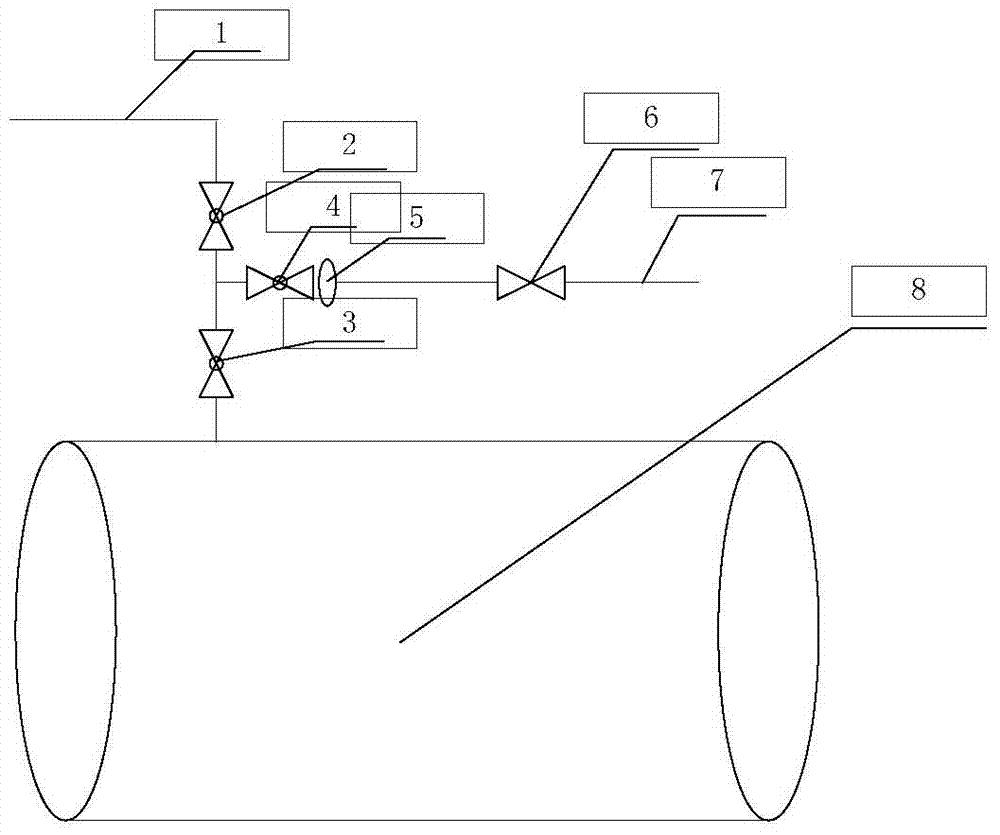
[0029] A cooling piping system using BOG, such as figure 1 , figure 2 As shown, it includes a cooled pipeline 8, an LNG pipeline 7 and a BOG gas pipeline 1; the top of the cooled pipeline 8 is provided with a first valve 3, and the LNG pipeline 7 and the BOG gas pipeline 1 are located at the first valve 3, and all communicate with the cooled pipeline 8 through the first valve 3; wherein,

[0030] The LNG pipeline 7 is provided with an orifice 5 .

[0031] The BOG gas phase pipeline 1 is provided with a BOG pipeline regulating valve 2 , and the BOG pipeline regulating valve 2 is close to one end of the BOG gas phase pipeline 1 communicating with the cooled pipeline 8 .

[0032] The LNG pipeline 7 is provided with...


PUM


Abstract

The invention relates to a system for cooling a pipeline through boil off gas (BOG). The system comprises the cooled pipeline, a liquefied natural gas (LNG) pipeline and a BOG gas-phase pipeline, wherein a first valve is arranged on the top of the cooled pipeline; the LNG pipeline and the BOG gas-phase pipeline are located above the first valve and are communicated with the cooled pipe through the first valve; the LNG pipeline is provided with a pore plate. By utilization of the system for cooling the pipeline through the BOG, influences on precooling of the pipeline by heavy component gathering are prevented, the cost is reduced, the pipeline cooling risks are reduced, and the precooling effect is improved.

Description

technical field [0001] The present invention relates to a system for cooling pipes using BOG. Background technique [0002] The liquefied natural gas (LNG) pipeline system is an important part of the LNG receiving station. Its normal operation is the condition to ensure the normal production of the LNG receiving station. Due to the low temperature and large size of the low-temperature pipeline in the LNG receiving station, its trial operation includes later maintenance. Putting into use has always been a difficult point in the industry, and LNG pipelines are usually made of austenitic stainless steel. Austenitic stainless steel has excellent low-temperature performance, but has a large coefficient of linear expansion. Under the LNG temperature condition, the shrinkage rate of stainless steel is about 3 / 1000. For the 304L material pipeline, when the working temperature is -162℃, the 100m pipeline shrinks about 300mm. In order to prevent the stress caused by cold shrinkage b...

Claims


Application Information

Patent Timeline
Patent Type & Authority Patents(China)
IPC IPC(8): F16L53/00
CPCF16L53/00
Inventor 王海伟黎晖林晓东林素辉刘浩庄楚平徐雷红张远杰
Owner 中海福建天然气有限责任公司
Why Eureka
Try Eureka