Manufacturing method of amorphous iron core
A technology of amorphous iron core and manufacturing method, which is applied in the direction of inductance/transformer/magnet manufacturing, transformer/inductor core, electrical components, etc., which can solve the problem of time-consuming forming operations, many fastening positions, and difficulty in ensuring iron core stacking Thickness value and other issues to achieve the effect of preventing the uneven thickness value of the iron core lamination, stabilizing the characteristics of the iron core, reducing the number of fixtures and man-hours
- Summary
- Abstract
- Description
- Claims
- Application Information
AI Technical Summary
Problems solved by technology
Method used
Image

Examples
Embodiment 1
[0031] use Figure 1 to Figure 6 A method of manufacturing the amorphous iron core according to Example 1 of the present invention will be described.
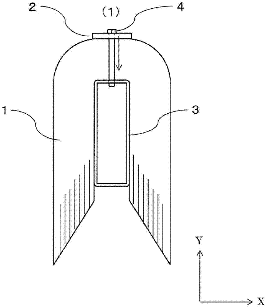
[0032] figure 1 It is a front view of the state after taking out the iron core from the cutting machine. The iron core 1 is constituted, for example, by stacking a plurality of amorphous alloy thin strips to form a unit laminate and arranging a plurality of the laminate around the inner core rod 3 . The iron core 1 is in an inverted U-shape with one side open. An inner mandrel 3 is installed on the inner peripheral side of the iron core, and the inner mandrel 3 and the back plate 2 are connected by bolts 4 . By implementing this connection without looseness, it is possible to prevent the iron core from opening, and to make the iron core lamination thickness value of the fastened portion an accurate value. also, figure 1 The arrows in indicate the direction of the bolt tightening force.
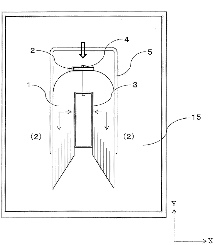
[0033] figure 2 It is a front ...
Embodiment 2
[0044] use Figure 7 Example 2 of the present invention will be described. In Example 2, the shape of the U-shaped side plate of Example 1 is modified. Figure 7 It is a front view of a state in which a U-shaped iron core molding side plate 9 is attached to the iron core 1, and a large arrow indicates a direction in which the side plate 9 is fitted, and a small arrow indicates a force application direction. The curved portion of the U-shaped side plate 9 has a shape along the R portion of the iron core.
[0045] According to this embodiment, by using the U-shaped side plate 9 , since the R portion of the iron core and the curved portion of the side plate are followed, deformation of the R portion of the iron core can be prevented. Thereby, the core characteristic can be stabilized. If the side plate is rectangular instead of U-shaped, there will be a gap between the R portion of the iron core and the clamp, and the iron core may hang down (expand) to this portion.
[0046]...
Embodiment 3
[0048] use Figure 8 , Figure 9 Embodiment 3 of the present invention will be described. In Example 3, the interval between the side plates in the U-shaped side plates of Example 1 is made variable. Figure 8 It is a front view of the state where the side plate variable jig is attached to the iron core, Figure 9 is a side view of the side and bottom plates of the side plate variable clamp. In addition, a large arrow indicates the direction in which the side plate variable jig 10 is embedded, and a small arrow indicates the direction of applying force.
[0049] The side plate variable jig 10 is formed of two pieces of side plates 10a and a bottom plate 10b. The protrusion 10aa of the side plate 10a of the variable side plate jig is inserted into the notch 10bb provided on the bottom 10b of the variable side plate jig, and the side plate 10a is connected to the jig connection position 10ba by the bottom plate connecting bolt 11 . By using a plurality of pre-prepared conne...
PUM
 Abstract
Description
Claims
Application Information
 - R&D
- Intellectual Property
- Life Sciences
- Materials
- Tech Scout
- Unparalleled Data Quality
- Higher Quality Content
- 60% Fewer Hallucinations
Browse by: Latest US Patents, China's latest patents, Technical Efficacy Thesaurus, Application Domain, Technology Topic, Popular Technical Reports.
© 2025 PatSnap. All rights reserved.Legal|Privacy policy|Modern Slavery Act Transparency Statement|Sitemap|About US| Contact US: help@patsnap.com