Plug connector

A technology of plug connectors and contactors, which is applied in the direction of connection, parts of connection devices, contact parts, etc., and can solve the problems of poor electrical connection between reed contact parts and electrode pads, poor yield, interference, etc.

Active Publication Date: 2016-03-02
ITT MFG ENTERPRISES LLC
View PDF13 Cites 2 Cited by
  • Summary
  • Abstract
  • Description
  • Claims
  • Application Information

AI Technical Summary

Problems solved by technology

That is, since the reed contact part of the contactor and the electrode pad of the substrate are manually fixed by soldering, the work takes a long time
Especially with multi-pole type plug connectors with multiple contacts, it takes longer
[0011] Also, if the plug connector is a multi-pole type with multiple contacts, the spacing between the contacts is narrow
Therefore, the reed contact parts of adjacent contactors may be electrically connected by soldering, and a problem of solder bridge (

Method used


Image

  • Plug connector
  • Plug connector
  • Plug connector

Examples


Example Embodiment

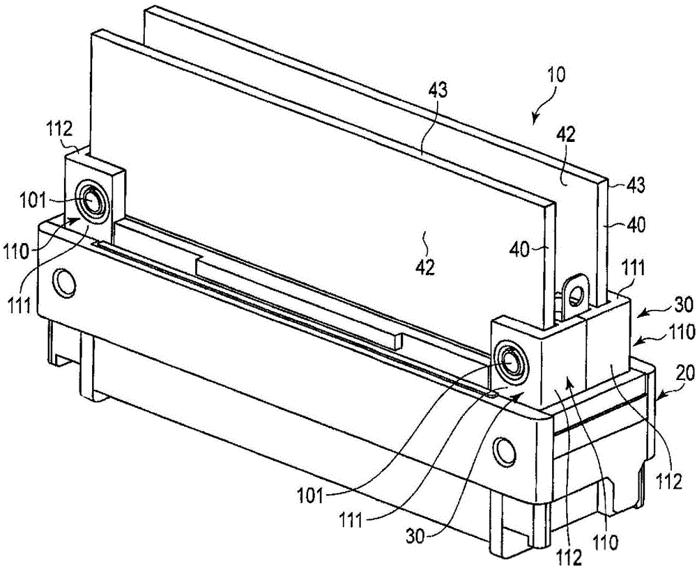
[0023] Below, use Figure 1 ~ Figure 6 Describes a plug connector according to an embodiment of the present invention. figure 1 It is a perspective view showing the plug connector 10. The plug connector 10 is used, for example, to connect electronic devices. More specifically, the plug connector 10 is provided in an electronic device, and is formed to be detachable and attachable to a socket connector provided in another electronic device.

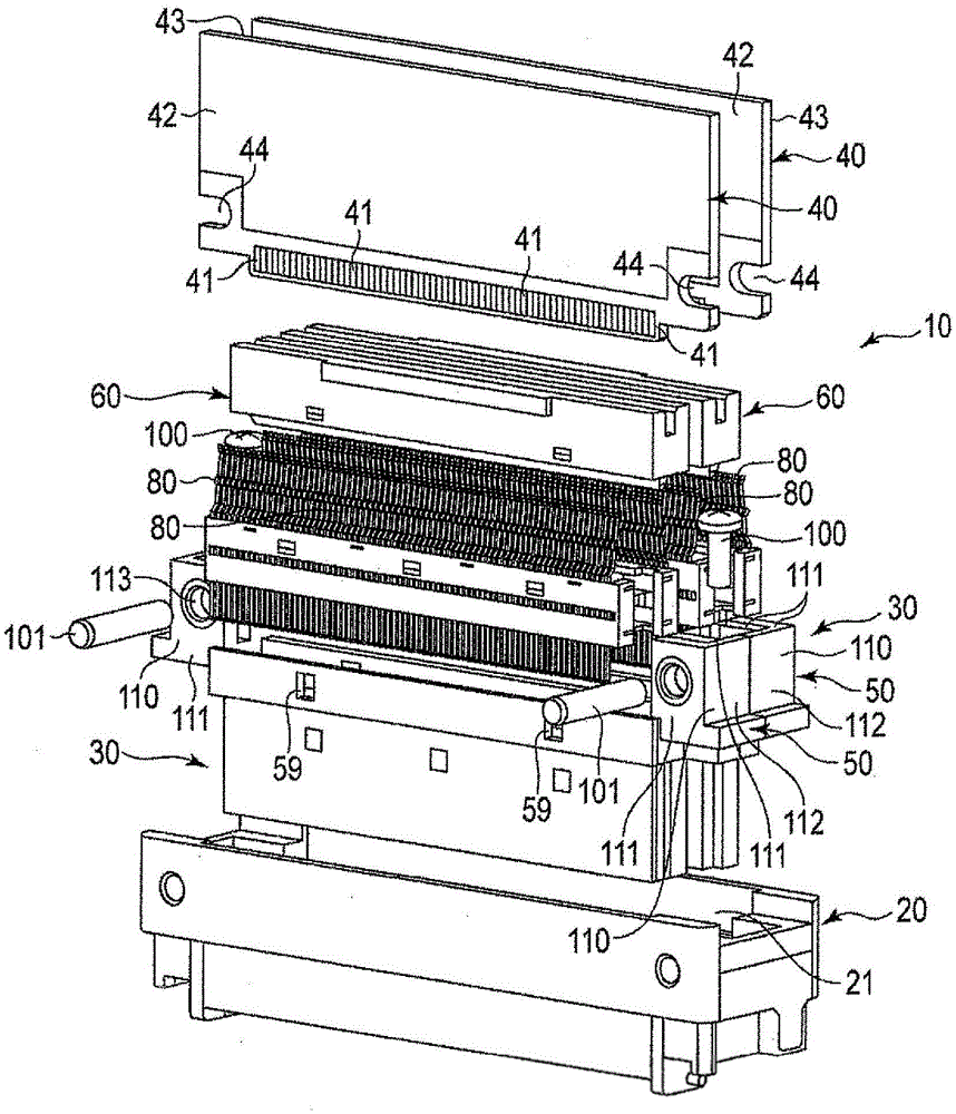
[0024] figure 2 It is an exploded perspective view showing a state in which the plug connector 10 is disassembled. Such as figure 1 , 2 As shown, the plug connector 10 has a housing 20 and a pair of sub-assemblies 30 housed in the housing 20. The sub-assembly 30 has the same structure as each other. Therefore, the two sub-assemblies are marked with the same symbols for description.

[0025] The sub-assembly 30 has a substrate 40 provided with a plurality of electrode pads 41, an insulator 50 that can accommodate the substrate 40, and a plu...


PUM


Abstract

The present invention provides a plug connector that can improve the efficiency of attaching work of a substrate, and improve the yield. The plug connector (10) includes a substrate (40), an insulator (50), a slider (60), and a contactor (80). The slider (60) is slidable between positions (90) and (91) inside the insulator (50). The contactor (80) is housed between an inner surface of a housing space part (65) of the slider (60) and a substrate receiver part (62). The substrate receiver part (62) fixes the lead contact part (87) of the contactor (80) to a position apart from an electrode pad (41) of the substrate (40) in a state where the slider (60) is located at the position (90) or fixes to a position where a pressing force of the lead contact part (87) against the electrode pad (41) is limited to not greater than a predetermined value, and releases fixation of the position when the slider (60) is moved from the position (90) to the position (91). The slider (60) presses the lead contact part (87) against the electrode pad (41) by pressing the contactor (80) when sliding.

Description

technical field [0001] The present invention relates to, for example, a plug connector including a plurality of contacts. Background technique [0002] For example, a multi-pole ZIF (Zero Insertion Force, zero insertion force) connector type plug connector has an insulator to which a plurality of contacts are fixed, and a substrate accommodated in the insulator. The base plate has electrode pads electrically connected to the contacts. The reed contact portion of the counter contactor and the electrode pads of the substrate are welded to each other to fix the electrical connection. By soldering and fixing the reed contact portion of the contactor and the electrode pad of the substrate, sufficient connection strength between the reed contact portion of the contactor and the electrode pad of the substrate can be obtained. [0003] Soldering between the reed contact portion of the contactor and the electrode pads of the substrate is generally performed manually using a solderi...

Claims


Application Information

Patent Timeline
IPC IPC(8): H01R12/72H01R13/627H01R13/639H01R13/11
CPCH01R12/89H01R12/721
Inventor 池中一夫
Owner ITT MFG ENTERPRISES LLC
Why Eureka
Try Eureka