Electric equipment protective device

A technology of electrical components and protection devices, applied in variable capacity pump components, pump components, liquid variable capacity machinery, etc., can solve problems such as bad, small gaps, leakage insulation, etc.

Inactive Publication Date: 2009-05-13
PANASONIC CORP
View PDF8 Cites 1 Cited by
  • Summary
  • Abstract
  • Description
  • Claims
  • Application Information

AI Technical Summary

Problems solved by technology

[0012] However, if the above-mentioned conventional structure is adopted, since the electrical component cover 30 is mounted on the surrounding frame 20 by one touch, a gap will be formed between the top surface portion of the electrical component cover 30 and the surrounding frame 20 near the compressor housing 10 . small gap
In this way, although the possibility of water infiltrating into the interior of the electrical component cover 30 is low when water flows down from the top of the electrical component cover 30 in mist form, when a large amount of water flows down, the water will pass through the top of the electrical component cover 30. The gap between the surface part and the surrounding frame 20 penetrates into the electrical component cover 30, adheres to the glass terminal 15 and the energized part of the electrical component 17, causes problems such as leakage and poor insulation, and makes the compressor unable to operate normally.

Method used


Image

  • Electric equipment protective device
  • Electric equipment protective device
  • Electric equipment protective device

Examples


Embodiment 1

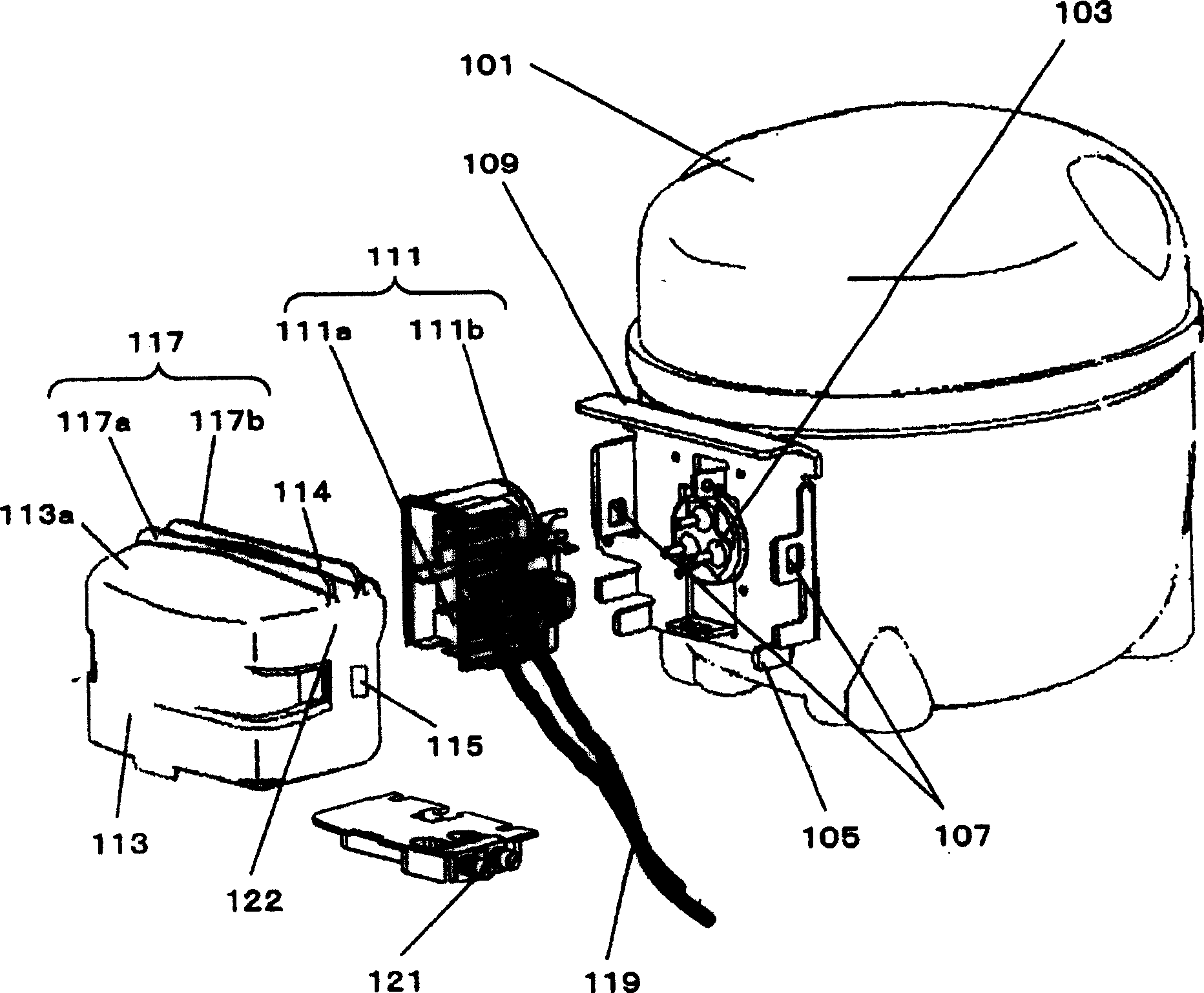
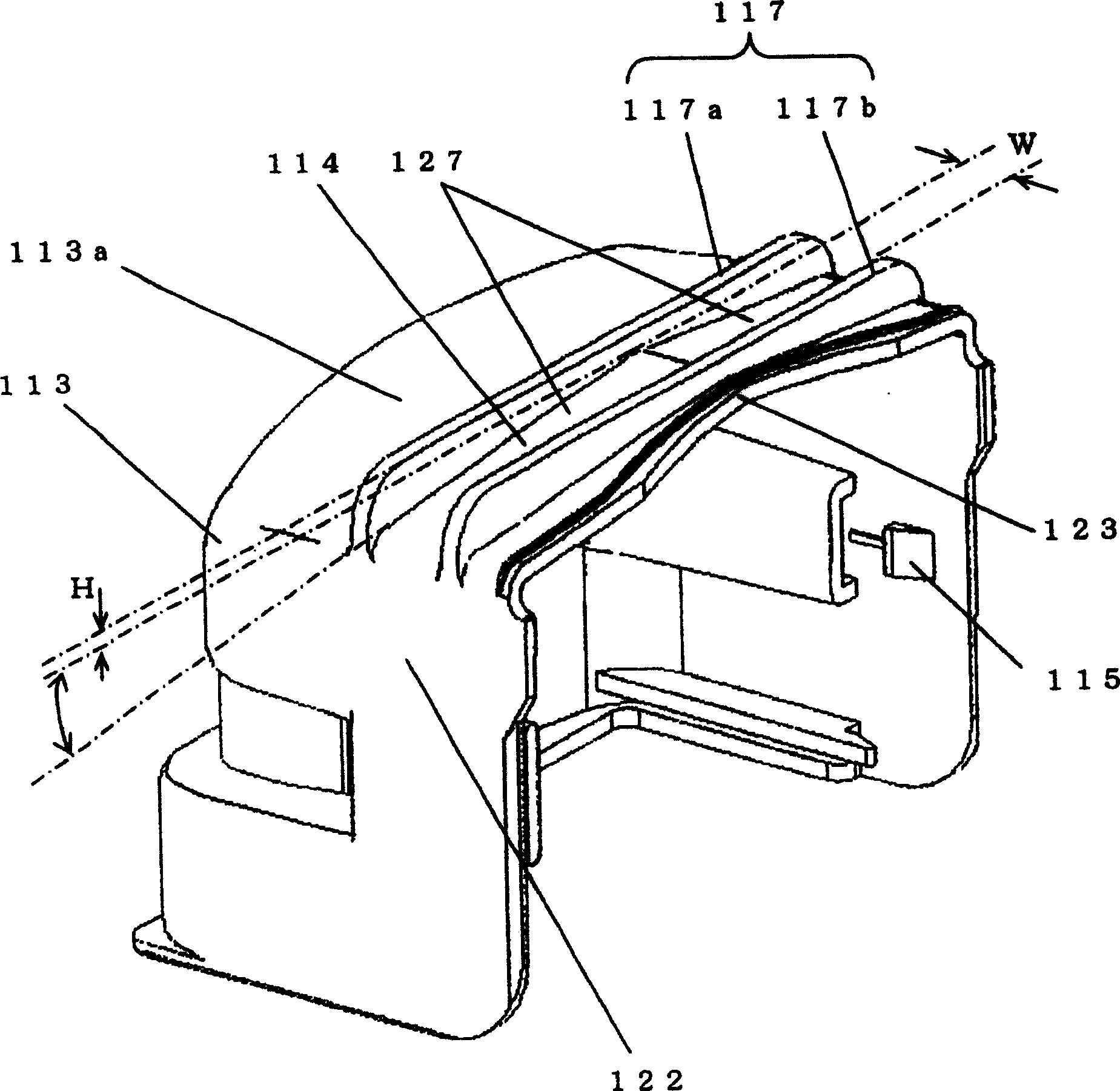
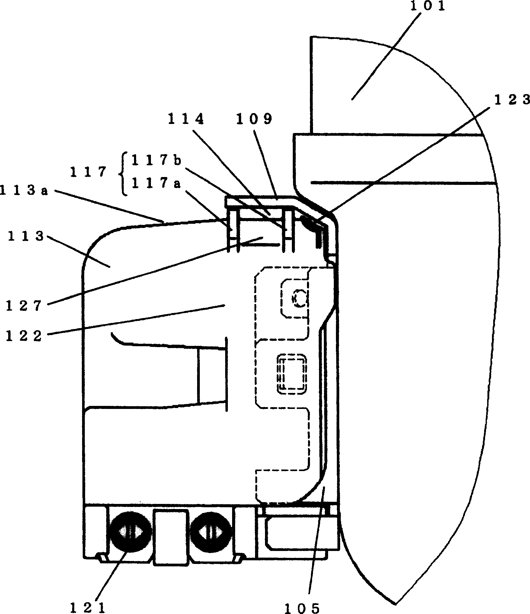
[0042] figure 1 It is an exploded oblique view of the electrical component protection device in Embodiment 1 of the present invention, figure 2 is an oblique view of the electrical parts cover, image 3 It is an enlarged schematic diagram of the electrical component protection device in the installed state, Figure 4 It is the experimental result graph of the second experiment.

[0043] A motor mechanism (not shown in the figure) and a compression mechanism (not shown in the figure) driven by the motor mechanism are installed inside the compressor casing 101 .

[0044] Such as Figure 1 to Figure 3 As shown in , the electrical components 111 include a starting relay 111a and a motor protector 111b. The purpose of using the starting relay 111a is to control the energization of the motor mechanism, so as to prevent the motor mechanism from being burned due to excessive current flowing.

[0045] Specifically, the motor mechanism is provided with a main winding (not shown i...

Embodiment 2

[0081] Figure 5 It is an exploded oblique view of the electrical component protection device according to Embodiment 2 of the present invention, Figure 6 is an oblique view of the electrical parts cover, Figure 7 It is an enlarged schematic diagram of the electrical component protection device in an installed state, Figure 8 It is a schematic diagram of the experimental results of the second experiment.

[0082] exist Figure 5 to Figure 7 Among them, an electric motor mechanism (not shown in the figure) and a compression mechanism (not shown in the figure) driven by the electric motor mechanism are installed inside the compressor casing 201.

[0083] The electrical components 211 include a starting relay 211a and a motor protector 211b. The purpose of using the starting relay 211a is to control the energization of the motor mechanism, so as to prevent the motor mechanism from being burned due to excessive current flowing.

[0084] Specifically, the motor mechanism is...

Embodiment 3

[0119] Figure 9 It is an exploded oblique view of the electrical component protection device in Embodiment 3 of the present invention, Figure 10 is an oblique view of the electrical parts cover, Figure 11 It is an enlarged schematic diagram of the electrical component protection device in the installed state, Figure 12 for along Figure 11 The cross-sectional view of line A—A in Figure 13 It is a schematic diagram of the experimental results of the second experiment.

[0120] exist Figure 9 to Figure 12 In the compressor casing 301, an electric mechanism (not shown in the figure) and a compression mechanism (not shown in the figure) driven by the electric mechanism are arranged inside the compressor housing 301.

[0121] The electrical components 311 include a starting relay 311a and a motor protector 311b. The purpose of using the starting relay 311a is to control the energization of the motor mechanism, so as to prevent the motor mechanism from being burned due t...


PUM


Abstract

A penetration of water into the electric equipment cover can be positively prevented without deteriorating the working property of one-touch inserting motion of the electric equipment cover and a highly reliable electric equipment protective device of compressor is provided. The electric equipment protective device of a compressor includes: an electric equipment cover 113 for accommodating the electric equipment 111; a hood portion 109 which is arranged in an upper portion of the electric equipment cover and closely fixed onto an outer surface of the compressor body 101; and a drain ditch 114 arranged at a position in an upper face portion 113a of the electric equipment cover opposed to the hood portion. Due to the above constitution, the penetration of water into the electric equipment cover can be positively prevented without deteriorating the working property of one-touch inserting motion of the electric equipment cover and a highly reliable electric equipment protective device of compressor is provided.

Description

technical field [0001] The present invention relates to an electric component protection device to be mounted on a compressor in a freezer or the like. Background technique [0002] Among the existing protective devices for electrical components, some can be fixed by a plug-in insertion operation (for an example, refer to Japanese Patent Laid-Open No. 2-33478). [0003] The above-mentioned conventional electrical component protection device will be described below with reference to the accompanying drawings. [0004] Figure 14 It is an exploded oblique view of the existing electrical component protection device in the above-mentioned references, Figure 15 is an enlarged side view of the electrical component protection device in an installed state, Figure 16 It is an enlarged top view of the electrical component protection device in an installed state. [0005] Such as Figure 14 to Figure 16 As shown in , a glass terminal 15 for supplying power to the motor mechanism ...

Claims


Application Information

Patent Timeline
Patent Type & Authority Patents(China)
IPC IPC(8): F04B39/00
CPCF04B39/12
Inventor 冈本贵之渡壁俊造
Owner PANASONIC CORP
Why Eureka
Try Eureka