Forming part manufacturing method and forming machine

A molding machine, molding technology, applied in the field of molding manufacturing and molding machines, to prevent the effect of preventing unacceptable input

Active Publication Date: 2016-03-09
ENGEL AUSTRIA
View PDF8 Cites 2 Cited by
  • Summary
  • Abstract
  • Description
  • Claims
  • Application Information

AI Technical Summary

Problems solved by technology

The disadvantage of this method is that these offsets can only be adjusted more or less correctly and quickly with the operator's long experience

Method used


Image

  • Forming part manufacturing method and forming machine
  • Forming part manufacturing method and forming machine
  • Forming part manufacturing method and forming machine

Examples


Embodiment Construction

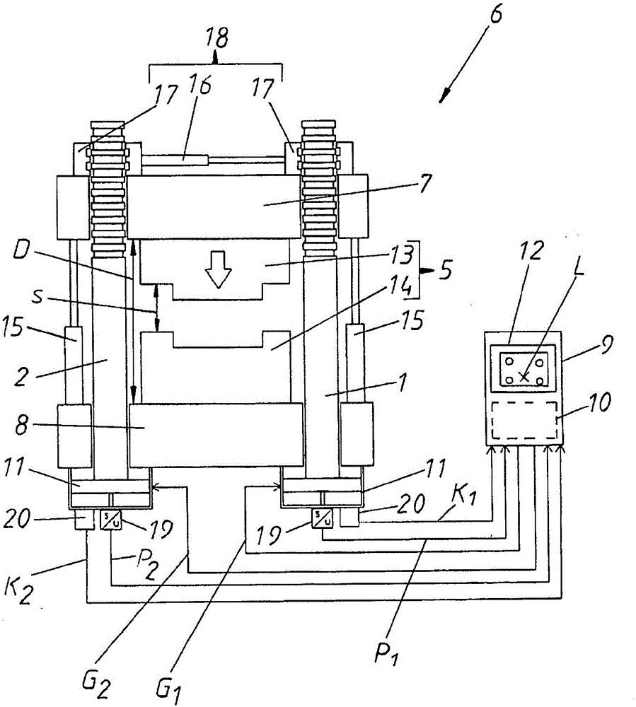
[0022] figure 1 A molding machine 6 is shown in the form of a vertical injection molding machine. The molding machine has a fixed mold clamping plate 8 , which is supported on supports, not shown. In addition, parallel to the fixed mold clamping plate 8, a movable mold clamping plate 7 is provided, which can move vertically along the beams 1 and 2 (and beams 3 and 4, which are not visible here). direction of movement. This vertical movability takes place via snap-action reciprocating devices 15 , which are formed, for example, as hydraulic piston-cylinder units. The distance D between the mold clamping plates 7 and 8 can be varied by means of a snap-action shuttle 15 .

[0023] In the upper region of the beams 1 and 2 are formed recesses and protrusions which cooperate with the recesses and protrusions of the connecting sleeve 17 . Together with a drive 16 , preferably a hydraulic piston-cylinder unit, this connecting sleeve 17 forms a locking device 18 for locking the mov...


PUM


Abstract

The invention relates to a method for injecting plastic or a plastic raw material into a mould cavity of a forming mould (5) of a forming machine (6) to manufacture a forming part. The forming mould (5) is disposed on two relatively movable mould clamping plates (7, 8) of the forming machine (6), and the mould clamping plates (7, 8) are orientated at least on part of relative movement portions of the mould clamping plates in a predetermined manner that the mould clamping plates tilt to each other. The forming mould is characterized in that the relative tilting posiiton degree of the two mould clamping plates (7, 8) is predetermined through a change of a position (x, y) of a force introduction point (L).

Description

technical field [0001] The invention relates to a method for producing molded parts by injecting plastic or plastic raw material into the cavities of the molding dies of a molding machine, wherein the molding dies are arranged clamped in two molds of the molding machine which are movable relative to each other and the two mold clamping plates can be oriented obliquely relative to each other in a predetermined manner at least over a portion of their movement relative to each other. The invention also relates to a molding machine, in particular an injection molding machine, having a fixed mold clamping plate, a mold clamping plate movable relative to said fixed mold clamping plate, a mold clamping plate arranged between said two molds Forming molds on a clamping plate and a control or regulation unit for controlling or regulating the relative movement of the mold clamping plates relative to each other, the two mold clamping plates being able to operate in a predetermined manner ...

Claims


Application Information

Patent Timeline
Patent Type & Authority Applications(China)
IPC IPC(8): B29C45/56B29C45/76
CPCB29C45/561B29C45/7653B29C2945/76083B29C2945/76381B29C2945/76234B29C2945/76505B29C45/80B29C2945/76013B29C2945/76254B29C2945/76568B29C2945/76712B29C2945/76732
Inventor H·施泰因帕泽H·蔡德尔霍费尔P·艾格
Owner ENGEL AUSTRIA
Why Eureka
Try Eureka