Wind deflector assembly for air conditioner and air conditioner

A technology of air deflectors and air conditioners, which is applied in the direction of airflow control components, etc., can solve the problems of poor comfort of air conditioners, achieve the effect of improving the comfort of use and realizing the effect of no wind feeling

Inactive Publication Date: 2016-03-09
GD MIDEA AIR-CONDITIONING EQUIP CO LTD +1
View PDF6 Cites 19 Cited by
  • Summary
  • Abstract
  • Description
  • Claims
  • Application Information

AI Technical Summary

Problems solved by technology

[0002] Users often turn on the cooling or heating function of the air conditioner to keep the indoor ambient temperature within a comfortabl

Method used


Image

  • Wind deflector assembly for air conditioner and air conditioner
  • Wind deflector assembly for air conditioner and air conditioner
  • Wind deflector assembly for air conditioner and air conditioner

Examples


Embodiment 1

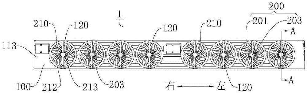
[0134] Such as Figure 1-Figure 5 As shown, in this embodiment, the air conditioner 2 includes a housing 21 , an air deflector 100 and eight groups of air diffuser assemblies 200 . The casing 21 has an air outlet 22 , and when the air conditioner 2 needs to cool, heat or ventilate the environment where it is located, the air can flow out from the air outlet 22 . The wind deflector 100 is pivotably disposed at the air outlet 22 , and the wind deflector 100 is provided with eight installation openings 110 corresponding to the eight air diffuser components 200 one by one. The air diffuser assembly 200 is suitable for making the air blown out from the air outlet 22 flow in a diffuse flow manner. It can be understood that the wind changes its original flow direction and flows in different directions after passing through the air diffuser assembly 200 .

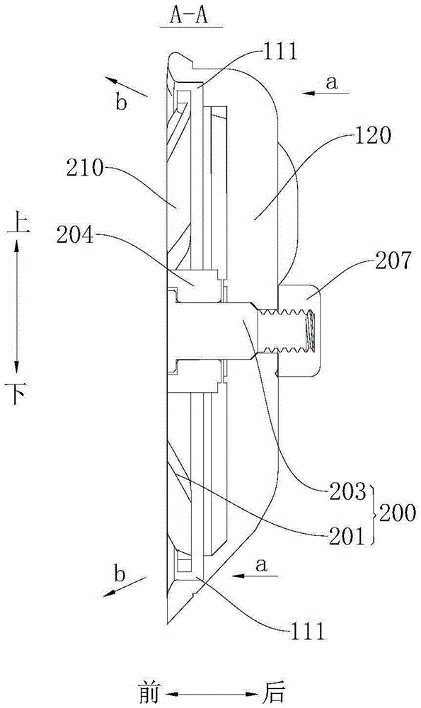
[0135] Such as Figure 5 As shown, the diffuser assembly 200 is rotatably installed at the installation opening 110 and includ...

Embodiment 2

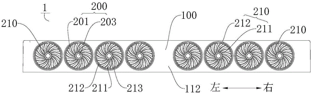
[0143] Such as Figure 6-Figure 9 As shown, the difference from Embodiment 1 is that in this embodiment, there are six groups of diffuser assemblies 200 , and the wind wheels 210 in each group of diffuser assemblies 200 include eight blades 211 and three connecting brackets 120 . One ends of the three connecting brackets 120 intersect at one point, and a mounting hole 121 is formed at this point, and one end of the pivot shaft 203 is adapted to pass through the mounting hole 121 . The other ends of the three connecting brackets 120 are respectively connected to the wind deflector 100 , and the three connecting brackets 120 are evenly distributed along the circumferential direction of the central wind ring 213 , that is, the angles between any two adjacent connecting brackets 120 are equal. In this way, not only the structural strength of the wind deflector 100 can be enhanced, but also the connection bracket 120 can be prevented from blocking the air outlet at the installation...

Embodiment 3

[0146] Such as Figure 10-Figure 13 As shown, the difference from Embodiment 1 is that in this embodiment, there are six groups of diffuser assemblies 200, and the wind wheels 210 in each group of diffuser assemblies 200 include twelve blades 211, and one connecting bracket 120 . One end of the connecting bracket 120 is connected to the wind deflector 100 , and the other end has a mounting hole 121 and is connected to the air diffuser body 201 through a pivot shaft 203 . In addition, in this embodiment, the threaded fastener 207 is sleeved on one end of the pivot shaft 203 in a ring shape, thereby simplifying the structure of the wind deflector 100 , reducing the mass of the wind deflector 100 , and saving production costs.

[0147] When the wind deflector 100 closes the air outlet 22 , the end surfaces of the blades 211 facing the outside of the casing 21 and the end surfaces of the wind guiding ring 212 facing outside the casing 21 are located on the same plane. Thus, the ...


PUM


Abstract

The invention discloses a wind deflector assembly for an air conditioner and the air conditioner. The wind deflector assembly comprises an wind deflector and at least one wind diffusion assembly, wherein the wind deflector is pivotally arranged at a wind outlet of the air conditioner, and at least one mounting port is formed in the wind deflector; the wind diffusion assembly is of a single-layer structure and is rotatably arranged on the mounting port to perform the diffusion and flowing for wind blown out from the wind outlet. According to the wind deflector assembly for the air conditioner, the at least one wind diffusion assembly is arranged on the wind deflector, thus the wind blown out from the wind diffusion assembly can flow in a diffusion manner, rather than being directly blown out in the same direction through the wind outlet, and as a result, the free-wind effect of the air conditioner can be realized, and the use comfort of the air conditioner can be improved.

Description

technical field [0001] The present invention relates to the technical field of air conditioning, in particular to a wind deflector assembly for an air conditioner and the air conditioner. Background technique [0002] Users often turn on the cooling or heating function of the air conditioner to keep the indoor ambient temperature within a comfortable range. If the wind with cold or hot air blows on people, they will feel the strong wind, which makes the air conditioner less comfortable. Especially in summer, when the air conditioner is cooling, the strong air-conditioning will make some weak people such as the elderly, pregnant women, and children prone to air-conditioning diseases. Contents of the invention [0003] The present invention aims to solve one of the technical problems in the related art at least to a certain extent. [0004] Therefore, the present invention proposes a wind deflector assembly for an air conditioner, which has the effect of guiding wind withou...

Claims


Application Information

Patent Timeline
IPC IPC(8): F24F13/08
CPCF24F13/08
Inventor 张浩刘奇伟谭周衡
Owner GD MIDEA AIR-CONDITIONING EQUIP CO LTD
Why Eureka
Try Eureka