Air deflector assembly for air conditioner and air conditioner
A technology of wind deflectors and air conditioners, which is applied in the direction of air flow control components, etc., and can solve the problems of poor comfort of air conditioners
- Summary
- Abstract
- Description
- Claims
- Application Information
AI Technical Summary
Problems solved by technology
Method used
Image
Examples
Embodiment 1
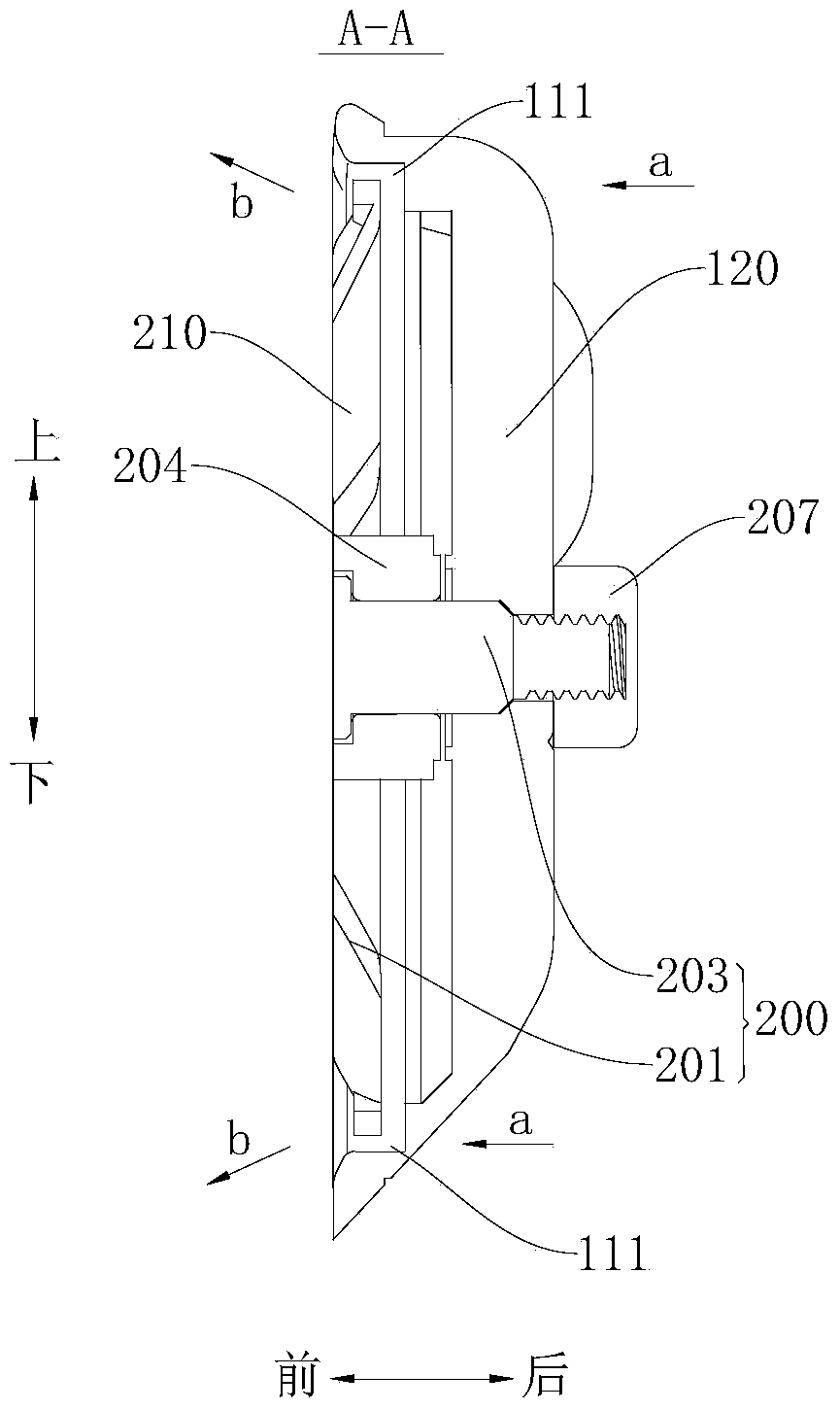
[0127] Such as Figure 1-Figure 5 As shown, in this embodiment, the air conditioner 2 includes a housing 21 , an air deflector 100 and eight groups of air diffuser assemblies 200 . The casing 21 has an air outlet 22 , and when the air conditioner 2 needs to cool, heat or ventilate the environment where it is located, the air can flow out from the air outlet 22 . The wind deflector 100 is pivotably disposed at the air outlet 22 , and the wind deflector 100 is provided with eight installation openings 110 corresponding to the eight air diffuser components 200 one by one. The air diffuser assembly 200 is suitable for making the air blown out from the air outlet 22 flow in a diffuse flow manner. It can be understood that the wind changes its original flow direction and flows in different directions after passing through the air diffuser assembly 200 .
[0128] Such as Figure 5 As shown, the diffuser assembly 200 is rotatably installed at the installation opening 110 and includ...
Embodiment 2
[0136] Such as Figure 6-Figure 9 As shown, the difference from Embodiment 1 is that in this embodiment, there are six groups of diffuser assemblies 200 , and the wind wheels 210 in each group of diffuser assemblies 200 include eight blades 211 and three connecting brackets 120 . One ends of the three connecting brackets 120 intersect at one point, and a mounting hole 121 is formed at this point, and one end of the pivot shaft 203 is adapted to pass through the mounting hole 121 . The other ends of the three connecting brackets 120 are respectively connected to the wind deflector 100 , and the three connecting brackets 120 are evenly distributed along the circumferential direction of the central wind ring 213 , that is, the angles between any two adjacent connecting brackets 120 are equal. In this way, not only the structural strength of the wind deflector 100 can be enhanced, but also the connection bracket 120 can be prevented from blocking the air outlet at the installation...
Embodiment 3
[0139] Such as Figure 10-Figure 13 As shown, the difference from Embodiment 1 is that in this embodiment, there are six groups of diffuser assemblies 200, and the wind wheels 210 in each group of diffuser assemblies 200 include twelve blades 211, and one connecting bracket 120 . One end of the connecting bracket 120 is connected to the wind deflector 100 , and the other end has a mounting hole 121 and is connected to the air diffuser body 201 through a pivot shaft 203 . In addition, in this embodiment, the threaded fastener 207 is sleeved on one end of the pivot shaft 203 in a ring shape, thereby simplifying the structure of the wind deflector 100 , reducing the mass of the wind deflector 100 , and saving production costs.
[0140] When the wind deflector 100 closes the air outlet 22 , the end surfaces of the blades 211 facing the outside of the casing 21 and the end surfaces of the wind guiding ring 212 facing outside the casing 21 are located on the same plane. Thus, the ...
PUM
 Abstract
Description
Claims
Application Information
 - R&D
- Intellectual Property
- Life Sciences
- Materials
- Tech Scout
- Unparalleled Data Quality
- Higher Quality Content
- 60% Fewer Hallucinations
Browse by: Latest US Patents, China's latest patents, Technical Efficacy Thesaurus, Application Domain, Technology Topic, Popular Technical Reports.
© 2025 PatSnap. All rights reserved.Legal|Privacy policy|Modern Slavery Act Transparency Statement|Sitemap|About US| Contact US: help@patsnap.com


