Circuit breaker switch DC resistance measuring device

A technology of circuit breaker switch and measuring device, applied in the direction of measuring device, measuring device casing, measuring electrical variables, etc., can solve the problems of inaccurate measurement, affecting work efficiency, causing fire, etc., achieving accurate measurement data and eliminating the need for disassembly and assembly process, improve work efficiency

Active Publication Date: 2018-03-16
STATE GRID CORP OF CHINA +1
View PDF12 Cites 0 Cited by
  • Summary
  • Abstract
  • Description
  • Claims
  • Application Information

AI Technical Summary

Problems solved by technology

If the DC resistance of the circuit breaker switch is too large, it will cause the contacts inside the switch to heat up, and in severe cases, it will cause a fire. Therefore, it is very necessary to test the DC resistance of the circuit breaker switch.
The current method used to measure the DC resistance of the handcart circuit breaker switch is to use two wire clips to clamp a plum blossom contact on the circuit breaker switch, and the lead wire is connected to the wire clip. This measurement method measures the internal contact of the switch. and the sum of the resistance values ​​of the two plum-blossom contacts, the measurement is inaccurate, so it cannot accurately reflect the DC resistance value of the circuit breaker switch, resulting in misjudgment of the measurement results, which will cause unnecessary losses to power production
If you want to measure accurately, you can only remove the plum blossom contact, and then install the plum blossom contact after the measurement is completed, but disassembling the plum blossom contact is very cumbersome, time-consuming and laborious, and affects work efficiency

Method used


Image

  • Circuit breaker switch DC resistance measuring device

Examples


Embodiment Construction

[0016] Below in conjunction with accompanying drawing and specific embodiment the present invention is described in detail:

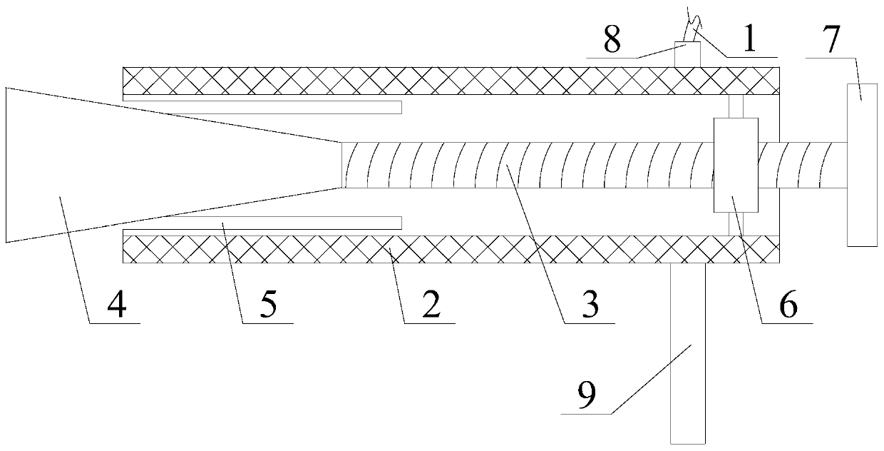
[0017] Specific examples, such as figure 1 As shown, the circuit breaker switch DC resistance measuring device includes a conductive device and a lead wire 1, the lead wire 1 is connected to the conductive device, the conductive device is connected to the cylindrical fixing rod of the plum blossom contact on the circuit breaker, and the conductive device includes a conductive cylinder 2, The outer diameter of the conductive cylinder 2 is less than the inner diameter of the cylindrical fixed rod of the plum blossom contact and the length of the conductive cylinder 2 is greater than the length of the plum blossom contact. The lead wire 1 is connected to the outer wall of the conductive cylinder 2 rear end. A platform-shaped support block 4, the side wall of the front end of the conductive cylinder 2 is provided with a plurality of gaps 5 along the circumf...


PUM


Abstract

A breaker switch direct current resistance measuring device. The outer diameter of a conductive cylinder is smaller than the inner diameter of a cylindrical fixed rod of a tulip contact and the length of the conductive cylinder is larger than that of the tulip contact, a lead is connected with an outer wall at the rear end of the conductive cylinder, the measuring device also includes a push-pull rod and a circular-truncated-cone-shaped supporting block, a plurality of notches are arranged on a side wall at the front end of the conductive cylinder along a circumferential direction, both the push-pull rod and the supporting block are located inside the conductive cylinder and the supporting block is located in front of the push-pull rod, the supporting block, the push-pull rod and the conductive cylinder are coaxially arranged, the diameter of the front end of the supporting block is larger than the inner diameter of the conductive cylinder and the diameter of the rear end is smaller than or equal to the inner diameter of the conductive cylinder, the front end of the push-pull rod is fixedly connected with the rear end of the conductive cylinder, and the rear end of the push-pull rod is located outside the conductive cylinder. Measured data are accurate, a direct current resistance value of a breaker switch can be reflected accurately, unnecessary loss is not caused to generation of electricity, a complicated process of dismounting and mounting the tulip contact is omitted, and the breaker switch direct current resistance measuring device is simple in structure and convenient to operate, and saves both time and labor.

Description

technical field [0001] The invention belongs to the technical field of electric power measuring tools, and relates to a device for measuring DC resistance of a circuit breaker switch. Background technique [0002] The safe and stable operation of the circuit breaker switch plays a very important role in the safety and reliability of the power supply system. If the DC resistance of the circuit breaker switch is too large, it will cause the contacts inside the switch to heat up, and in severe cases, it will cause a fire. Therefore, it is very necessary to test the DC resistance of the circuit breaker switch. The current method used to measure the DC resistance of the handcart circuit breaker switch is to use two wire clips to clamp a plum blossom contact on the circuit breaker switch, and the lead wire is connected to the wire clip. This measurement method measures the internal contact of the switch. and the sum of the resistance values ​​of the two plum-blossom contacts, the...

Claims


Application Information

Patent Timeline
Patent Type & Authority Patents(China)
IPC IPC(8): G01R27/02G01R1/04
Inventor 周兆辉苏丛辉师威刘立强赵之洞周建军刘伟良袁继森安英娟檀志峰尹翠华张广平吕乐乐石赛亮师进冲
Owner STATE GRID CORP OF CHINA
Why Eureka
Try Eureka