Stamping method and method of manufacturing a stamped part
A stamping forming and component technology, which is applied to vehicle components, transportation and packaging, etc., can solve problems such as cracks on the outer panel and poor stamping formability
- Summary
- Abstract
- Description
- Claims
- Application Information
AI Technical Summary
Problems solved by technology
Method used
Image
Examples
no. 1 approach
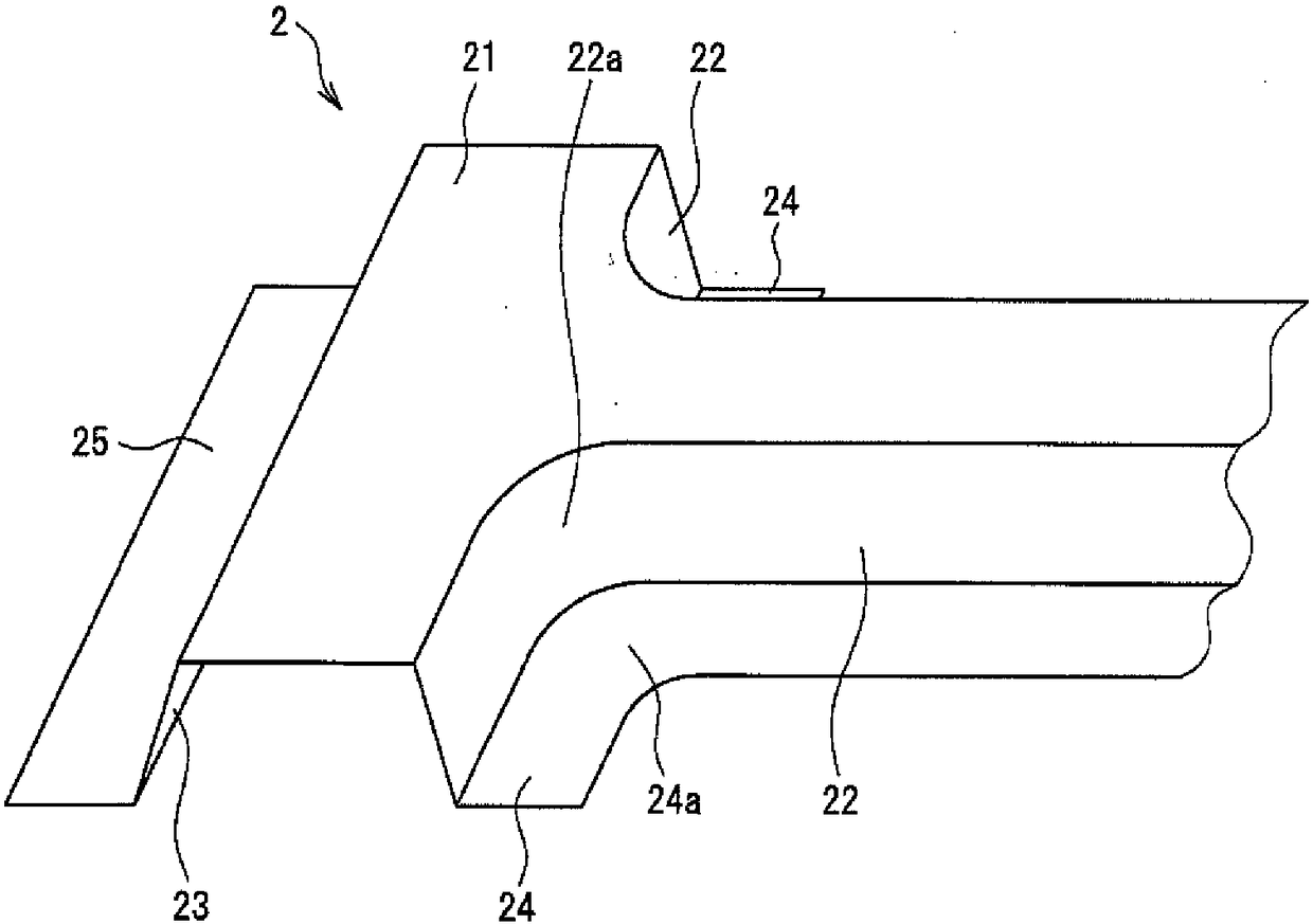
[0072] In this embodiment, making image 3 Curved pipe parts of the shape shown. Such a curved duct member is used, for example, as a center pillar member of an automobile.
[0073] Such as image 3As shown, the curved duct member 2 consists of a top plate portion 21 corresponding to the base, a vertical wall portion 22 having a curved portion 22a, a vertical wall portion 23 without a curved portion, and a flange portion continuous with the vertical wall portion 22 having a curved portion 22a. 24 and a flange portion 25 that is continuous with the vertical wall portion 23 without a bend. The flange portion 24 has a curved portion 24 a at a portion continuous with the curved portion 22 a of the vertical wall portion 22 .
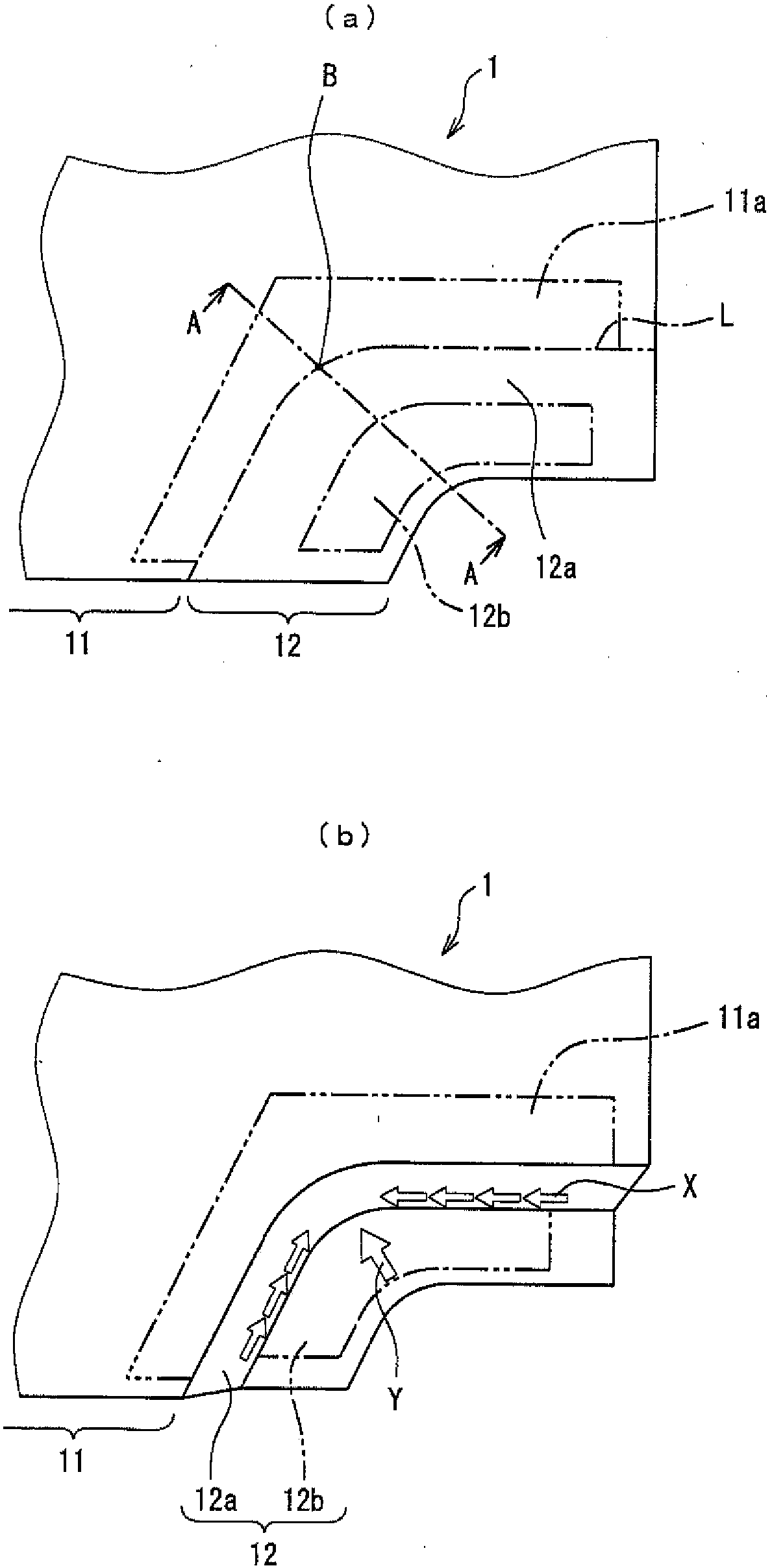
[0074] The vertical wall portion 22 having the bent portion 22 a of the curved duct member 2 and the flange portion 24 continuous thereto are formed by the following method. Here, portions other than the bent portion 22a may be formed by a normal drawing ...
no. 2 approach
[0084] Also in this embodiment, it is produced in the same manner as in the first embodiment image 3 The curved pipe part 2 of the shape shown. The vertical wall portion 22 having the curved portion 22a of the curved pipe member 2 and the flange portion 24 continuous therewith pass through Image 6 The following method is shown for formation.
[0085] The method of this embodiment differs from the method of the first embodiment in the method of moving the wrinkle-preventing plate 33 and the second backing plate 34 that restrain the outer portion 12b, and other parts are the same as the method of the first embodiment.
[0086] First, if Image 6 As shown by the solid line in the center, the boundary side portion 11a of the base 11 of the blank 1 is clamped and constrained by the punch 31 and the first backing plate 32, and the deformation portion 12 is clamped and constrained by the anti-wrinkle pressure plate 33 and the second backing plate 34. Outer part (portion to be th...
no. 3 approach
[0096] Also in this embodiment, it is produced in the same manner as in the first embodiment image 3 The curved pipe part 2 of the shape shown. The vertical wall portion 22 having the curved portion 22a of the curved pipe member 2 and the flange portion 24 continuous therewith pass through Figure 7 The following method is shown for formation.
[0097] The metal mold used in stamping is basically the same as Figure 4 same, but as Figure 7 As shown, a punch 35 having a convex portion 35 a on a side surface (a pressing surface that contacts the vertical wall portion) is disposed below the blank 1 . A second backing plate 36 having a concave portion 36 a on a side surface is disposed above the anti-crease platen 33 . Other parts are the same as the second embodiment.
[0098] Similar to the method of the second embodiment, the anti-crease plate 33 and the second backing plate 36 constraining the outer portion 12b are oriented at an angle (θ) of 30° to 60° with respect to ...
PUM
| Property | Measurement | Unit |
|---|---|---|
| height | aaaaa | aaaaa |
Abstract
Description
Claims
Application Information
 - R&D
- Intellectual Property
- Life Sciences
- Materials
- Tech Scout
- Unparalleled Data Quality
- Higher Quality Content
- 60% Fewer Hallucinations
Browse by: Latest US Patents, China's latest patents, Technical Efficacy Thesaurus, Application Domain, Technology Topic, Popular Technical Reports.
© 2025 PatSnap. All rights reserved.Legal|Privacy policy|Modern Slavery Act Transparency Statement|Sitemap|About US| Contact US: help@patsnap.com


