Press molding method

A technology of stamping forming and vertical wall, which is applied in the field of stamping and forming, and can solve problems such as cracks on the outer panel and poor stamping formability

Active Publication Date: 2016-03-09
JFE STEEL CORP
View PDF8 Cites 13 Cited by
  • Summary
  • Abstract
  • Description
  • Claims
  • Application Information

AI Technical Summary

Problems solved by technology

In this case, the aluminum alloy tends to be inferior in press formability compared to the steel plate, and therefore, cracks may occur in the outer panel when performing press forming accompanied by stretch flange deformation.

Method used


Image

  • Press molding method
  • Press molding method
  • Press molding method

Examples


no. 1 approach

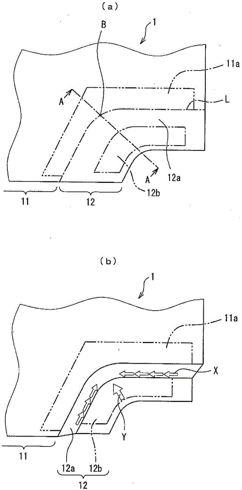
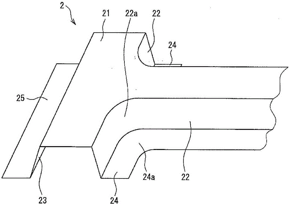
[0072] In this embodiment, making image 3 Curved pipe parts of the shape shown. Such a curved duct member is used, for example, as a center pillar member of an automobile.

[0073] Such as image 3As shown, the curved duct member 2 consists of a top plate portion 21 corresponding to the base, a vertical wall portion 22 having a curved portion 22a, a vertical wall portion 23 without a curved portion, and a flange portion continuous with the vertical wall portion 22 having a curved portion 22a. 24 and a flange portion 25 that is continuous with the vertical wall portion 23 without a bend. The flange portion 24 has a curved portion 24 a at a portion continuous with the curved portion 22 a of the vertical wall portion 22 .

[0074] The vertical wall portion 22 having the bent portion 22 a of the curved duct member 2 and the flange portion 24 continuous thereto are formed by the following method. Here, portions other than the bent portion 22a may be formed by a normal drawing ...

no. 2 approach

[0084] Also in this embodiment, it is produced in the same manner as in the first embodiment image 3 The curved pipe part 2 of the shape shown. The vertical wall portion 22 having the curved portion 22a of the curved pipe member 2 and the flange portion 24 continuous therewith pass through Figure 6 The following method is shown for formation.

[0085] The method of this embodiment differs from the method of the first embodiment in the method of moving the wrinkle-preventing plate 33 and the second backing plate 34 that restrain the outer portion 12b, and other parts are the same as the method of the first embodiment.

[0086] First, if Figure 6 As shown by the solid line in the center, the boundary side portion 11a of the base 11 of the blank 1 is clamped and constrained by the punch 31 and the first backing plate 32, and the deformation portion 12 is clamped and constrained by the anti-wrinkle pressure plate 33 and the second backing plate 34. Outer part (portion to be ...

no. 3 approach

[0096] Also in this embodiment, it is produced in the same manner as in the first embodiment image 3 The curved pipe part 2 of the shape shown. The vertical wall portion 22 having the curved portion 22a of the curved pipe member 2 and the flange portion 24 continuous therewith pass through Figure 7 The following method is shown for formation.

[0097] The metal mold used in stamping is basically the same as Figure 4 same, but as Figure 7 As shown, a punch 35 having a convex portion 35 a on a side surface (a pressing surface that contacts the vertical wall portion) is disposed below the blank 1 . A second backing plate 36 having a concave portion 36 a on a side surface is disposed above the anti-crease platen 33 . Other parts are the same as the second embodiment.

[0098] Similar to the method of the second embodiment, the anti-crease plate 33 and the second backing plate 36 constraining the outer portion 12b are oriented at an angle (θ) of 30° to 60° with respect to ...


PUM

PropertyMeasurementUnit
heightaaaaaaaaaa

Abstract

The present invention provides a method for manufacturing a bent channel component having a bend in a vertical wall thereof by press molding, the method mitigating stretch flange deformation, which occurs in the vertical wall portion and a flange portion. This method for manufacturing a bent channel component has a shearing deformation step as a step for forming the vertical wall portion. In the shearing deformation step, a boundary portion (11a) between a base (11) and a deformed portion (12) of a blank (1), and an external portion (12b) of the deformed portion (12) are separately restrained, a portion (12a) to be a vertical wall of the deformed portion (12) is shear-deformed along the plate surface thereof, and a material is caused to flow from a portion separated from the bend to the bend (movement of material in the blank) in an outer edge of the portion (12a) to be the vertical wall.

Description

technical field [0001] The present invention relates to a press forming technique for forming a press-formed part having a curved vertical wall, such as a curved pipe part. In particular, the present invention is a technique suitable for press forming of the bent portion of the vertical wall portion that deforms along with the forming of the elongated flange. Background technique [0002] In recent years, steel sheets with higher strength have been demanded in order to balance the crash safety of automobiles with the weight reduction of vehicle bodies. However, as the tensile strength increases, the steel sheet tends to decrease in ductility, which is largely related to press formability. Therefore, studies have been made on press-formed products that can be formed into shapes that can be formed even from poorly ductile steel sheets, such as simplified shapes, and / or press-forming methods suitable for high-strength steel sheets. [0003] In the case of press-forming a high...

Claims


Application Information

Patent Timeline
Patent Type & Authority Applications(China)
IPC IPC(8): B21D22/26B21D22/20
CPCB21D22/20B21D5/06B21D19/08B21D25/00B21D53/88B21D22/02
Inventor 藤井祐辅新宫礼久岸上靖广饭冢荣治山崎雄司
Owner JFE STEEL CORP
Why Eureka
Try Eureka