A bending springback compensation mold

A technology of mold and bending back, which is applied in the field of stamping molds, can solve problems such as the inapplicability of parts, and achieve the effect of eliminating stamping marks

Inactive Publication Date: 2017-09-01
HISENSE (SHANDONG) AIR CONDITIONING CO LTD
View PDF6 Cites 4 Cited by
  • Summary
  • Abstract
  • Description
  • Claims
  • Application Information

AI Technical Summary

Problems solved by technology

However, the bending mold of this structure can only form parts with a small bending edge height, and is not suitable for parts with a high bending edge height.

Method used


Image

  • A bending springback compensation mold
  • A bending springback compensation mold
  • A bending springback compensation mold

Examples


Embodiment Construction

[0025] The specific implementation manners of the present invention will be further described in detail below in conjunction with the accompanying drawings.

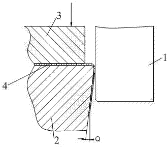
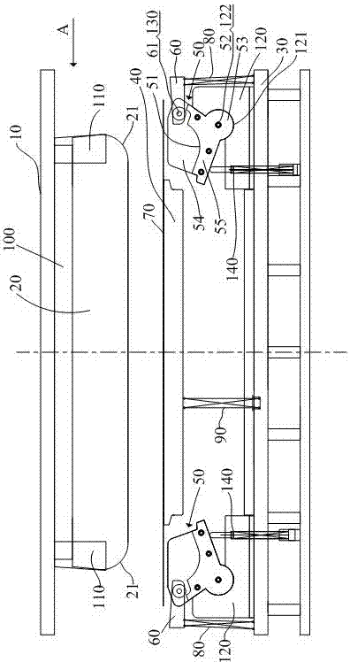
[0026] refer to Figure 3 to Figure 6 , a bending springback compensation mold in this embodiment includes an upper mold and a lower mold. The upper mold includes an upper mold base 10 and a punch 20 arranged on the upper mold base 10. The punch 20 has a bending angle with the workpiece. The bottom angle 21 is matched, and has a bending compensation angle Q; the lower mold includes a lower mold base 30, a lower stripper plate 40, a stripper plate return spring 90 and a rotatable swing at the left and right ends of the lower stripper plate 40 The die 50, the swing die 50 can be installed on the lower die base 30, and has a bending groove 51 adapted to the bottom angle 21 of the punch. Reset mechanism 140, on the swinging die 50, a swinging block 60 is swingably installed, and the swinging fulcrum 61 of the swinging block...


PUM


Abstract

The invention discloses a bending springback compensation mold. An upper mold comprises an upper mold seat and a convex mold, wherein the convex mold is provided with a bottom angle adaptive to a part bending angle; the convex mold is also provided with a bending compensation angle. A lower mold comprises a rotatable concave mold, wherein the rotatable concave mold is mounted on a lower mold seat and provided with a bending groove which is adaptive to the bottom angle of the convex mold; and a first return mechanism for returning the rotatable concave mold is arranged on the lower mold seat. A swinging block is mounted on the rotatable concave mold. In the mold closing process, the upper mold moves from top to bottom, the convex mold compresses a material stripping plate, the material stripping plate drives the rotatable concave mold to rotate, the swinging block swings with the rotating of the concave mold in the initial state of closing, and a push block on the upper mold begins to be in contact with the swinging block with the closing of the mold. When the mold is closed into place, the push block is positioned on the internal side of the swinging block, and the lower end of the push block abuts on the internal side surface of the swinging block. According to the invention, as the bending springback angle of the part can be accurately controlled and stamping marks of straight bent edge are also eliminated through the adoption of the swinging block, the bending springback compensation mold is especially suitable for bending and molding parts with large straight bent edge heights.

Description

technical field [0001] The invention belongs to the technical field of stamping dies, and in particular relates to a bending springback compensation die which can effectively perform springback compensation when the bending radius is large and the height of the bending edge is large, and realize precise control of the bending angle. Background technique [0002] In the stamping process, it is usually defined figure 1 The inner radius r of the bending arc shown in is the bending radius, and the angle a is the bending angle. Since the material has elastic deformation and plastic deformation at the same time during bending, after the stamping load is removed, the elastic deformation will recover, so that the bending radius r and bending angle a of the part change, respectively increasing to figure 1 R and A shown in , so that the shape of the workpiece is not consistent with the mold, that is, the expected bending angle and bending radius cannot be achieved. This phenomenon is...

Claims


Application Information

Patent Timeline
Patent Type & Authority Patents(China)
IPC IPC(8): B21D7/06B21D37/10
CPCB21D7/06B21D37/10
Inventor 李玉乾
Owner HISENSE (SHANDONG) AIR CONDITIONING CO LTD
Why Eureka
Try Eureka